



Tightening torques (Nm)
| Bolts and nuts | M6 | 9 |
| M7 | 15 | |
| M8 | 20 | |
| M10 | 40 | |
| M12 | 65 |
Engine to manual transmission
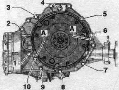
| Pos. | Bolt | Nm |
| 1 (1) | M10x50 (2) | 65 |
| 2 (3) | M12X100 (4) | 30 + 90° |
| 3 (5), 6 | M12x75 (4) | 30 + 90° |
| 4, 5 (5) | M12x120 (4) | 30 + 90° |
| 7...9 | M10x75 (4) | 15 + 90° |
| 10 | M12x50 (4) | 30 + 90° |
| A | Alignment bushings | |
(1) Additionally secures the starter.
(2) The bolt strength class is 10.9, the steel bolt can be used repeatedly.
(3) Additionally secures the starter; with an additional spacer sleeve between the starter and the gearbox.
(4) Bolts can be used twice.
(5) Additionally secures the wire holder.
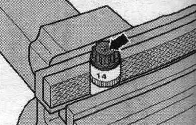
Aluminum bolts "2...10" may be used twice. Therefore, after single use of the bolts, make 2 notches "X" "arrow". To avoid damaging the bolts, do not clamp them in a vice. Insert the bolt as shown in the illustration into the 14 mm socket with a 1/2-inch extension, the other end of which is clamped in a hand vice. Bolts marked with "X" must not be reused.
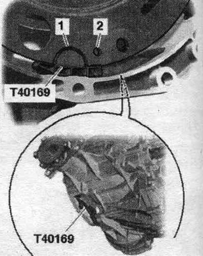
Replace bolts that were tightened with additional tightening. Replace self-locking nuts, lip seals, gaskets and seals. o-rings. On vehicles with a manual transmission, a needle bearing must be installed in the driven disk. Before installing the disc, make sure the needle bearing is installed. Press the needle bearing into the driven disk. Secure all hose connections with hose clamps of the appropriate series. During installation, all cable ties should be placed in their original locations. Before securing the engine to the gearbox, you must do the following: Insert the mounting. insert the "T40169" tool into the gearbox housing from below and install the dual mass flywheel as shown in the figure. The mounting tool should fit into the semicircular recess "1" and additionally into the inspection hole "2." To locate the inspection hole, it is necessary to rotate the dual mass flywheel. Insert mounting bolts. devices into the hole on the gearbox housing.
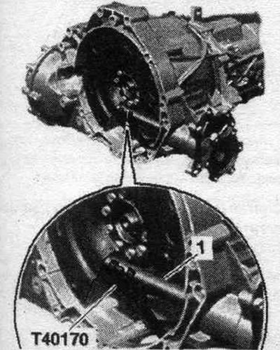
Insert the "T40170" transport bracket from below into the gearbox housing and secure it to the shaft with flange "1." If necessary, check the reusability of the aluminum engine mounting bolts on the gearbox and mark them.
Make sure that the installation bushings "A" for aligning the engine and gearbox in the cylinder block are present; if necessary, insert the missing bushings. Install the engine on the gearbox, screw in and tighten bolts "2...6". Bolt "2" secures the starter to the gearbox and has an additional. the "arrow" spacer sleeve. The spacer sleeve should be inserted between the starter and the gearbox. Unload the "10-222 A/11" lead screw. Lower the crane and place the engine and gearbox on the engine mounts. Screw on the engine mount. Remove the crane and suspension device. Tighten the bolts "1, 7, 8, 9, 10" engine and transmission connections. Remove transport lock "T40170" and mounting tool "T40169." This step is necessary to ensure the clutch module fits evenly on the driven disc and does not warp. Install the mudguards. Install the front wheels. Engage 4th gear and rotate the front wheels in the direction of travel until the clutch module makes a full revolution. The inspection hole "arrow" should be visible again in the recess of the gearbox housing.
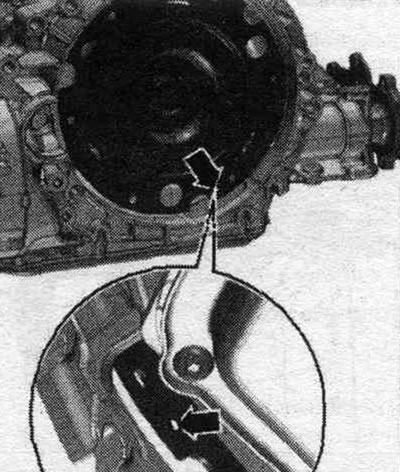
Secure the clutch module on the driven disc as follows: screw in the first bolt "arrow" by hand (2 Nm). Turn the front wheels in the direction of travel until the clutch module has turned 240°. In this position, tighten the accessible bolt to the specified torque. Rotate the front wheels in the direction of travel until the clutch module has rotated 120° respectively and tighten the remaining 2 bolts to the specified torque. Installation in reverse order. Install a diesel particulate filter. Install the differential pressure sensor "G505". Install the generator. Install a vane pump. Install the compressor. Install the poly V-belt. Install the counter support and crossbar. Install the front wall of the water drainage box. Install the air casing. filter. Electrical connections and wiring. Install the engine control unit. Install electrical wires, distributor 2 for terminal 30 "TV22" and the cover of the switching unit in the engine. compartment. Install the washer reservoir filler neck. Observe precautions after connecting the battery. Do not use a battery charger to start the engine! Connect the air duct hoses using threaded clamps. Check the oil level. Remove air from fuel. system. Connect the coolant hoses using the nipple connectors. Fill with coolant. Install soundproofing screens.
(The original article is available on the online resource audimanual.ru)