
Repair Chevrolet Repair Toyota Repair Honda Repair AvtoVAZ Repair Mercedes-Benz Repair BMW Repair Opel
Home  |  Contacts  |  Sitemap  |    
English Русский
Български
Беларускі
Український
Српски
Hrvatski
Română
Polski
Slovenský
Magyar
AudiManual.ru


  • AUDI 80
  • AUDI 100
  • AUDI A3
  • AUDI A4
  • AUDI A6
  • AUDI A8
  • AUDI Q
  • OTHER
  • ARTICLES
B8 (2007-2015) B7 (2004-2008) B6 (2000-2006) B6 (2000-2006, petrol) B5 (1994-2001) B5 (1994-2001, petrol)

Removal the engine (Audi A4 B8)

  • Home
  • Audi A4
  • B8 (2007-2015)
  • Power unit
  • Diesel engines 2.0 l (CJCB)
  • Removal the engine
            0
More details see previous 2.0L engine.

Note: The engine is removed upwards without the gearbox. When reassembling, reinstall all cable ties in their original locations. Follow the instructions when disconnecting the battery terminals.


Disconnect ground wire "2" from the battery terminal.
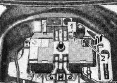
Disconnect ground wire «2» from the battery terminal.


Remove the "arrow" engine cover.
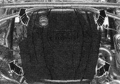
Remove the «arrow» engine cover.


Open the expansion lid. tank. Remove the front right and front left fender liner.
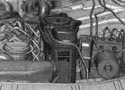
Open the expansion lid. tank. Remove the front right and front left fender liner.


Remove noise insulation screens "1" and "2".
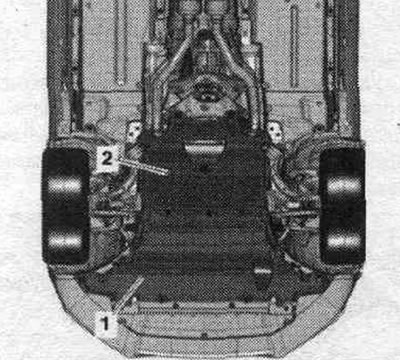


Remove noise insulation screens «1» and «2».


Place a service tray under the engine. Screw drain cock "1" to the fitting and drain the coolant, then remove fitting "2" from the radiator by lifting the mounting bracket. Release the coolant hose on the side member.
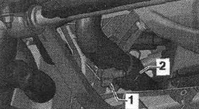
Place a service tray under the engine. Screw drain cock «1» to the fitting and drain the coolant,…


Remove the air duct hose and push it to the side; to do this, loosen the "arrow" clamp.
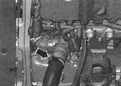
Remove the air duct hose and push it to the side; to do this, loosen the «arrow» clamp.


Unscrew the exhaust pipe "arrow" nuts.
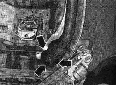


Unscrew the exhaust pipe «arrow» nuts.


Do not bend the connecting elements of the front exhaust pipe more than 10°. Unscrew the threaded connections "arrows", slide the clamping sleeve back and remove the exhaust pipe.
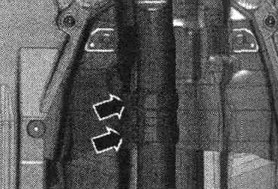
Do not bend the connecting elements of the front exhaust pipe more than 10°. Unscrew the threaded…


Unscrew bolt "2" of the diesel particulate filter suspension. "Pos. 1" should not be taken into account.
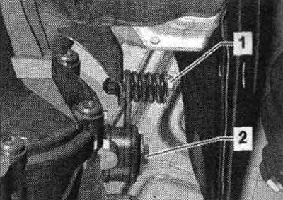
Unscrew bolt «2» of the diesel particulate filter suspension. «Pos. 1» should not be taken into…


If present, disconnect the "arrow" plug connection on the steering gear.
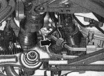


If present, disconnect the «arrow» plug connection on the steering gear.


Bring the lock mounting beam into service. position. Unscrew bolts "1" and remove the front engine mount. Unscrew the bolts on the left and right "2" and remove the cross member "3".
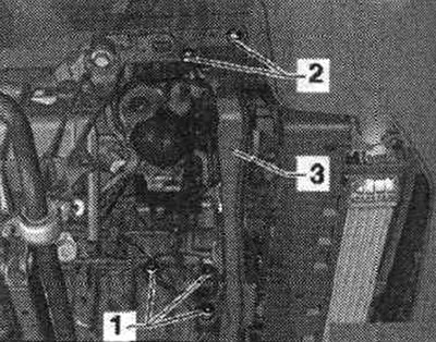
Bring the lock mounting beam into service. position. Unscrew bolts «1» and remove the front engine…


Remove cover "1" from the bottom of the "arrow" gearbox.
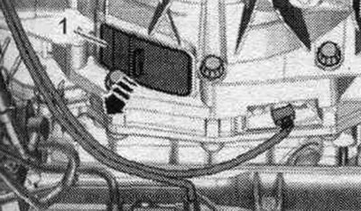
Remove cover «1» from the bottom of the «arrow» gearbox.


Remove the cap from the vibration damper. To loosen the driven disk bolts, use the bent open-end wrench "1" to hold the central bolt on the vibration damper. During the final turn, rotate the crankshaft only in the direction of engine rotation "arrow".
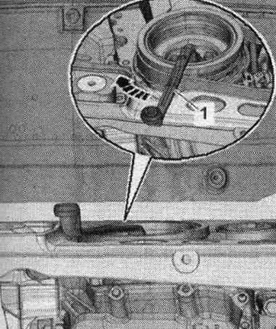


Remove the cap from the vibration damper. To loosen the driven disk bolts, use the bent open-end…


Unscrew the 3 bolts "arrow" of the driven disk, to do this, turn the crankshaft in 120° increments in the direction of engine rotation.
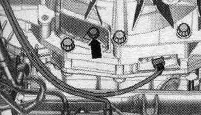
Unscrew the 3 bolts «arrow» of the driven disk, to do this, turn the crankshaft in 120° increments…


Unscrew the bolts "1, 7, 8, 9, 10" engine and gearbox connections. "Pos. A" should not be taken into account. Turn the tensioner element clockwise "arrow", remove the compressor V-belt from the pulley and lock the tensioner element with the retainer "T40098". Remove the poly V-belt.
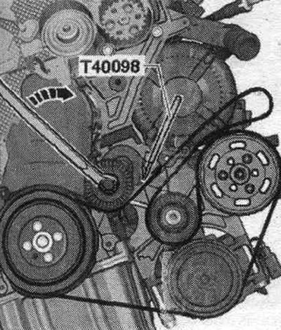
Unscrew the bolts «1, 7, 8, 9, 10» engine and gearbox connections. «Pos. A» should not be taken…


Disconnect plug connections "1" and "2" and release the electrical wires. Unscrew the compressor "arrow" bolts. Tie the compressor with the connected lines to the side. "Pos. 3" should not be taken into account.
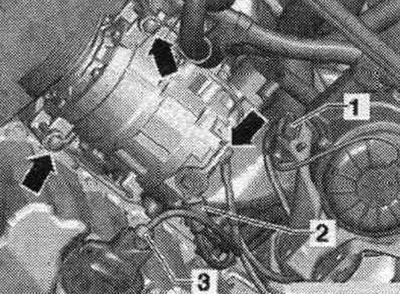


Disconnect plug connections «1» and «2» and release the electrical wires. Unscrew the compressor…


Remove the plug connection "1" of the radiator fan from the mount by moving the lock back "arrow" and pressing the stopper down. Release the radiator fan control unit wire harness.
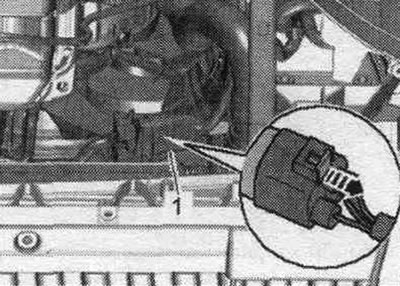
Remove the plug connection «1» of the radiator fan from the mount by moving the lock back «arrow»…


Unscrew the "arrow" nut on the right side member and release the ground wires.
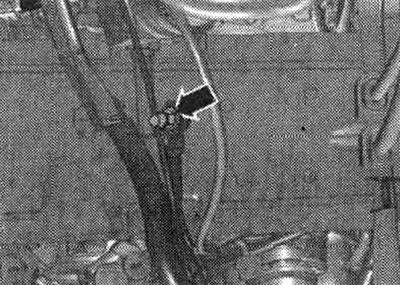
Unscrew the «arrow» nut on the right side member and release the ground wires.


Remove the coolant hoses by loosening the fastening clamps "1" and "3". Ignore "Pos. 2" and the "arrows".
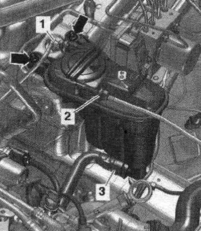


Remove the coolant hoses by loosening the fastening clamps «1» and «3». Ignore «Pos. 2» and the…


Remove the air duct hose by loosening the hose clamps "arrows". Disconnect the plug connection of the charge pressure sensor "G31" / intake manifold air temperature sensor "G42" "pos. 1" and release the wiring.
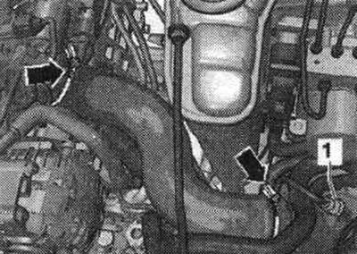
Remove the air duct hose by loosening the hose clamps «arrows». Disconnect the plug connection of…


Disconnect plug connection "3" of the air flow meter "G70". Remove the air duct hose from the air flow meter "G70" by loosening the hose clamp "4". Disconnect the vacuum hose "arrow". Remove the air flow meter housing. filter "2" and, if present, disconnect the plug connection "1" on its reverse side from the air bypass damper valve. filter "N275".
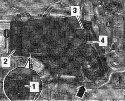
Disconnect plug connection «3» of the air flow meter «G70». Remove the air duct hose from the air…


For reinstallation, mark the position of the poly V-belt pulley of the vane pump in relation to the hub "arrow".
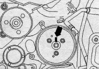


For reinstallation, mark the position of the poly V-belt pulley of the vane pump in relation to the…


Unscrew the "arrow" bolts, using a 2-hole "3212" wrench as a support, and remove the poly V-belt pulley of the impeller pump.
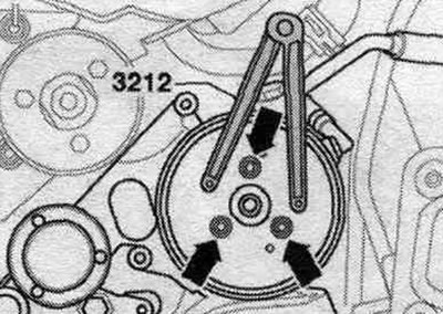
Unscrew the «arrow» bolts, using a 2-hole «3212» wrench as a support, and remove the poly V-belt…


Unscrew the "arrow" bolts and tie up the vane pump with the connected hydraulics. highways to the side.
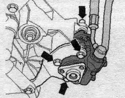
Unscrew the «arrow» bolts and tie up the vane pump with the connected hydraulics. highways to the…


Remove the coolant hose by loosening the fastening clamp "2". Ignore "Pos. 1".
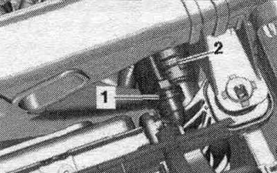
Remove the coolant hose by loosening the fastening clamp «2». Ignore «Pos. 1».


Remove the fuel hoses by loosening the hose clamps.
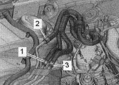
1. Fuel hose is yellow. 2. Fuel hose is blue. 3. The fuel hose is white.

1. Fuel hose is yellow. 2. Fuel hose is blue. 3. The fuel hose is white.


Remove the foam elements "1" from the left and right in an upward direction.
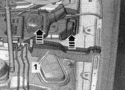
Remove the foam elements «1» from the left and right in an upward direction.


Remove the cover of the water drainage box "1".
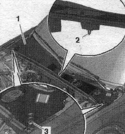
Remove the cover of the water drainage box «1».


Unlock the lock "arrow A" and open the cover "arrow B".
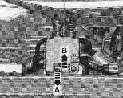
Unlock the lock «arrow A» and open the cover «arrow B».


Loosen the nuts on wires "1...3." Remove plug connection "4" from its holder and disconnect it. Unscrew bolt "5" and remove branch pipe 2 cl. 30 "TV22" from the front wall of the "arrow" water drainage box.
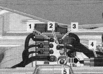
Loosen the nuts on wires «1...3.» Remove plug connection «4» from its holder and disconnect it.…


Disconnect the plug connection from the brake booster pressure sensor "G294" "arrow".
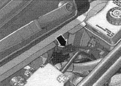
Disconnect the plug connection from the brake booster pressure sensor «G294» «arrow».


Unlock the retainers from the wheel arch using a 5.5 open-end wrench "pos. 1" and remove the cable entry "2" upwards. Release the wire bundle "3" to the generator and starter using the release lever "80-200".
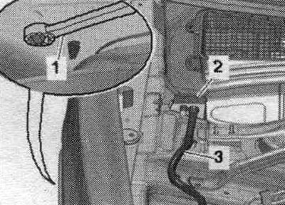
Unlock the retainers from the wheel arch using a 5.5 open-end wrench «pos. 1» and remove the cable…


Open cable channel "1" by unlocking the "arrow" latch and releasing the bundle of wires.
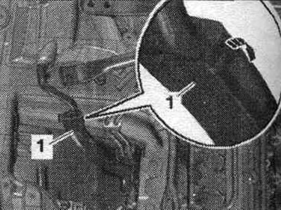
Open cable channel «1» by unlocking the «arrow» latch and releasing the bundle of wires.


Remove the vacuum pipe "1" from the end wall of the water drainage box; to do this, disconnect the vacuum hose "2" on the rear side of the "arrow".
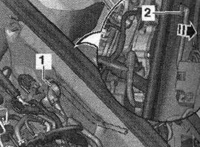
Remove the vacuum pipe «1» from the end wall of the water drainage box; to do this, disconnect the…


Unscrew the nut "1" and tilt the filler neck of the washer fluid reservoir slightly upwards "arrow A". Remove the filler neck "2" with the filler tube from the washer fluid reservoir, passing it through the body opening "arrow B".
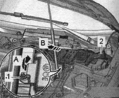
Unscrew the nut «1» and tilt the filler neck of the washer fluid reservoir slightly upwards «arrow…


On a vehicle with an independent heater, unscrew bolts "2" and put aside pump block "1".
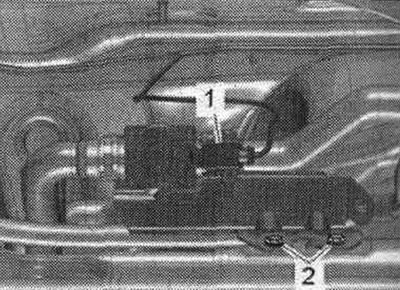
On a vehicle with an independent heater, unscrew bolts «2» and put aside pump block «1».


Unscrew the arrow bolts and remove the cover of the motorcycle switching unit. compartment. Unscrew nut "1" and release the wire.

Unscrew the arrow bolts and remove the cover of the motorcycle switching unit. compartment. Unscrew…


Unlock the "arrow A" fasteners and remove the "arrow B" engine control unit.
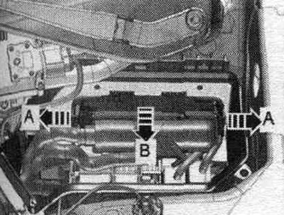
Unlock the «arrow A» fasteners and remove the «arrow B» engine control unit.


Disconnect (if available) plug connection "2". Disconnect plug connections "4" and unscrew wire fastening nut "3". Unlock the "arrow" latches and remove the relay and fuse "1" holders. Remove and free the engine wire harness secured in the switch. engine compartment block.
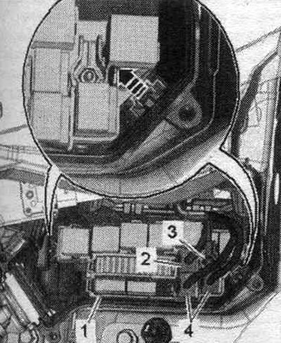
Disconnect (if available) plug connection «2». Disconnect plug connections «4» and unscrew wire…


Unlock the retainers "arrows A" and remove the cable guide "2" upwards "arrow B". Release the wiring harness, place it on the engine and secure the engine control unit against falling. "Pos. 1" should not be taken into account.
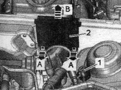
Unlock the retainers «arrows A» and remove the cable guide «2» upwards «arrow B». Release the…


Cars without independent heating: Unscrew nut "5". Remove the coolant hoses by loosening fastening clamps "1, 2". Route the coolant hoses through the front wall of the water drain box and release them. "Pos. 3, 4" do not take into account.
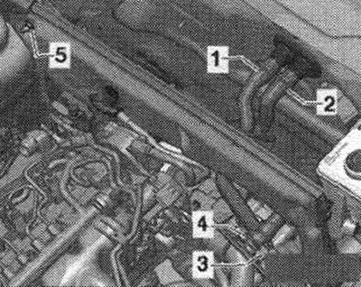
Cars without independent heating: Unscrew nut «5». Remove the coolant hoses by loosening fastening…


Cars with independent heating: Unscrew nut "3". Remove the coolant hoses by loosening hose clamps "1, 2". Route the coolant hoses through the front wall of the water drain box and release them.
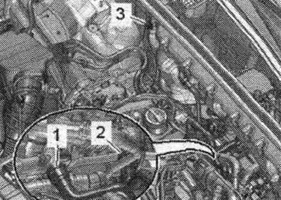
Cars with independent heating: Unscrew nut «3». Remove the coolant hoses by loosening hose clamps…


All


Remove the front wall of the water drainage box. Disconnect plug connection "3" of differential pressure sensor "G505". Unscrew bolt "2" and release hoses "1" from the holder. Place the differential pressure sensor "G505" back.
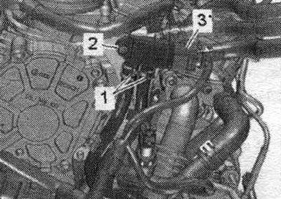
Remove the front wall of the water drainage box. Disconnect plug connection «3» of differential…


Release the "arrow" wire harness. Unscrew nuts "1" and remove holder "2". Remove the lambda probe.
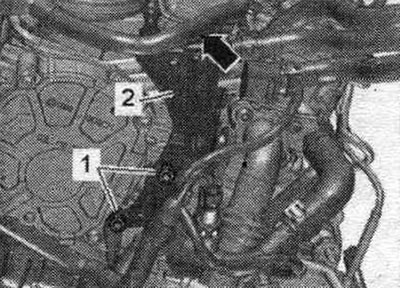
Release the «arrow» wire harness. Unscrew nuts «1» and remove holder «2». Remove the lambda probe.


Remove the plug connector from the bracket and disconnect it:
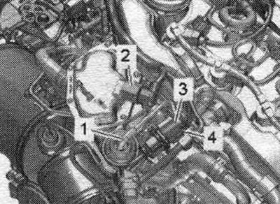
4. For exhaust gas temperature sensor 3 «G495». «Pos. 1, 2» do not take into account.

4. For exhaust gas temperature sensor 3 "G495". "Pos. 1, 2" do not take into account.


Unscrew the "arrow" nuts and put the particulate filter back.
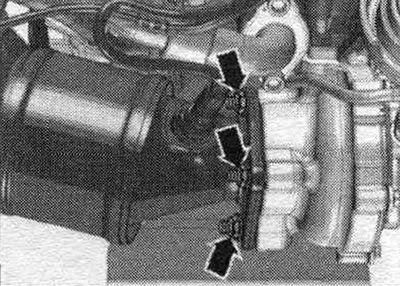
Unscrew the «arrow» nuts and put the particulate filter back.


Disconnect plug connection "2" from the reversing light switch "F4" and release the wire. "Pos. 1, 3" do not take into account.
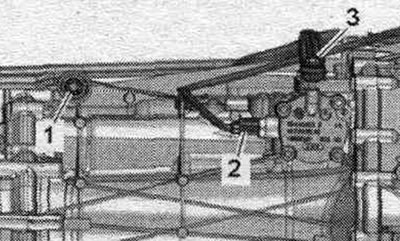
Disconnect plug connection «2» from the reversing light switch «F4» and release the wire. «Pos. 1,…


Unclip electrical wire "A" from the gearbox and disconnect plug connection "C". Ignore "Pos. B".
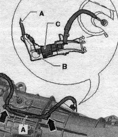
Unclip electrical wire «A» from the gearbox and disconnect plug connection «C». Ignore «Pos. B».


Disconnect the "arrow" plug connection from the gearbox neutral sensor -G701 - and release the wire.
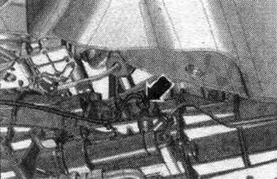
Disconnect the «arrow» plug connection from the gearbox neutral sensor -G701 - and release the wire.


Unscrew bolts "2...6" connecting the gearbox and the engine. Remove the starter from the gearbox and leave it in the mounting position. position. "Pos. A" should not be taken into account. Bolt "2" secures the starter to the gearbox and has an additional. spacer sleeve "arrow".
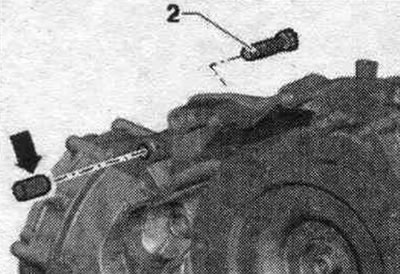
Unscrew bolts «2...6» connecting the gearbox and the engine. Remove the starter from the gearbox…


Install the "10-222 A" crossmember on the shock absorber strut cups on the left and right, as shown in the figure. Attach the "10-222 A/12" earrings to the gearbox and thread the "10-222 A/11" lead screw through. For a better understanding of the installation. the position is shown with the engine removed. Slightly tighten the gearbox using the lead screw of the traverse "10-222 A/11".
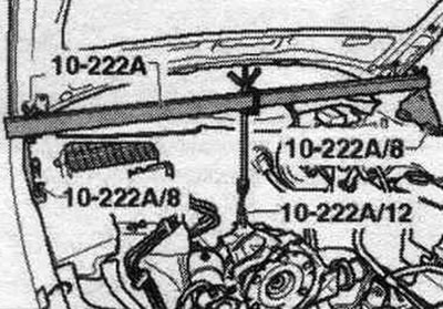
Install the «10-222 A» crossmember on the shock absorber strut cups on the left and right, as shown…


Remove the eye of the "2024 A" suspension device by disconnecting the pin and pressing in the bolt. Reinstall the eyelet into the 4th hole on the front of the hanging fixture. Secure the bolt with a stud. Attach the "2024 A" suspension device to the engine and the "VAS 6100" service crane as shown in the figure.
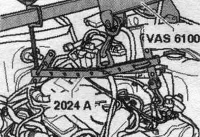
Remove the eye of the «2024 A» suspension device by disconnecting the pin and pressing in the bolt.…


Unscrew the bolts "1" of the engine mount on the left and right. Unscrew nut "2" and release the holder with electrical wires. Remove the left and right "arrow" plug connections from the holder and disconnect them. Raise the engine enough to clear the engine mounts. Tighten the lead screw "10-222 A/11". Ensure that all hose and wire connections between the engine, gearbox, subframe, and body are disconnected. When removing the engine from the motorcycle. be careful when entering the compartment.
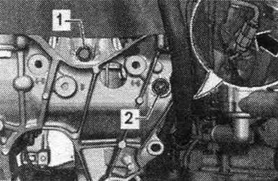
Unscrew the bolts «1» of the engine mount on the left and right. Unscrew nut «2» and release the…


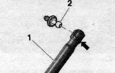
While removing engine 2, the mechanic must carefully open the hood, ensuring the maximum opening angle. To do this, lightly pry up the retaining spring "arrow" on the left and right with a small screwdriver and remove the gas-filled shock absorber "1" from the top of the ball joints "2". Disconnect the engine from the gearbox and lift it upwards from the engine. compartment. Press the gas-filled shock absorbers back into the ball joints.
While removing engine 2, the mechanic must carefully open the hood, ensuring the maximum opening…
The article was checked by auto expert Timur Bazhenov
This article is available at russian, bulgarian, belarusian, ukrainian, serbian, croatian, romanian, polish, slovak, hungarian

Share information:
Previous articles
Audi A4 B8: Diesel engines 2.0 l (CJCB)
Next articles

Engine number and specifications
Engine installation
Engine and gearbox mounting elements — removal and installation
Cylinder block from the belt pulley side
Pistons and connecting rods — general information


Similar articles on other Audi car models:
Engine hood Audi 80 B3 (1986-1991, petrol)
Cold Engine Idle Speed Adjustment Audi 100 C3 (1982-1990, diesel)
Starting the engine from an auxiliary power source Audi A3 Type 8L (1996-2003)
Draining engine oil Audi A6 C5 (1997-2004)
Starting the engine Audi A8 D2 (1994-2002)
Engine number Audi Q5 Type 8R (2008-2017)
Towing to start the engine Audi A2 (1999-2005)
Link to this page in different formats


Visitor comments

No comments yet


How much will 25 + 48 =


A4(B8, 2007-2015) 
  • General information
  • Operating instructions
  • Power unit
  • Petrol engines 1.8 l
  • Petrol engines 1.8/2.0 l
  • Petrol engines 3.0 l
  • Petrol engines 3.2 l
  • Fuel system (petrol)
  • Diesel engines 2.0 l (CA*)
  • Diesel engines 2.0 l (CJCB)
  • Diesel engines 2.7/3.0 l
  • Diesel engines 3.0 l
  • Fuel system (diesel)
  • Transmission
  • Manual gearbox 0B1
  • Manual gearbox 0B2
  • Manual gearbox 0B3
  • Manual gearbox 0B4
  • Automatic transmission 0B5
  • Automatic transmission 0B6
  • Automatic transmission 0AW
  • All-wheel drive system
  • Chassis
  • Front suspension
  • Rear suspension
  • Brake system
  • Steering system
  • Body
  • Exterior
  • Interior
  • Seats
  • Doors, locks and windows
  • Security system
  • Heating and air conditioning
  • Electrical equipment
  • Audio system
  • Power devices
  • Equipment and devices
  • Lighting and lamps
  • Electrical circuits
 
A4(B7, 2004-2008) 
  • General information
  • Introduction to manual
  • Troubleshooting
  • Operating instructions
  • Maintenance
  • Power unit
  • Petrol engines 2.0 (ALT)
  • Petrol engines 2.0 (TFSI)
  • Petrol engines 1.8 (MPI)
  • Diesel engines
  • Cooling system
  • Air conditioner
  • Fuel and exhaust system
  • Ignition system
  • Starting and charging
  • Transmission
  • Clutch
  • Manual gearbox
  • Automatic gearbox
  • Drive shafts
  • Chassis
  • Brake system
  • Front suspension
  • Rear suspension
  • Steering
  • Body
  • Exterior
  • Interior
  • Electrical equipment
  • Equipment and devices
  • Lighting and signaling
  • Windscreen wipers and washers
  • Electrical diagrams
  • Electrical diagrams (since 2007)
 
A4(B6, 2000-2006) 
  • General information
  • Vehicle Description
  • User manual
  • Maintenance
  • Power unit
  • Gasoline engine
  • Diesel engine
  • Lubrication system
  • Cooling system
  • Supply system
  • Injection system
  • Exhaust system
  • Ignition and control
  • Transmission
  • Gear box
  • Clutch and drive shafts
  • Chassis
  • Brake system
  • Car suspension
  • Steering
  • Body
  • Heating and ventilation
  • Exterior (external elements)
  • Interior (internal elements)
  • Electrical equipment
  • Power devices
  • Lighting and appliances
  • Electrical circuits
 
A4(B6, 2000-2006, petrol) 
  • General information
  • Introduction to the guide
  • Car care
  • Power unit
  • Engine repair
  • Lubrication system
  • Cooling system
  • Injection and control system
  • Ignition system
  • Power and exhaust system
  • Transmission
  • Clutch and drive shafts
  • Car gearbox
  • Chassis
  • Suspension and wheels
  • Steering
  • Brake system
  • Body
  • Interior
  • Exterior
  • Electrical equipment
  • Equipment and devices
  • Lighting and signaling
  • Power devices
  • Electrical circuits
 
A4(B5, 1994-2001) 
  • General information
  • Introduction to the guide
  • Car care
  • Maintenance (gasoline)
  • Maintenance (diesel)
  • Power unit
  • Gasoline engines
  • Diesel engines
  • Engine overhaul
  • Cooling system
  • Fuel injection (gasoline)
  • Fuel system (diesel)
  • Exhaust system
  • Ignition system
  • Transmission
  • Clutch
  • Mechanical gearbox
  • Automatic gearbox
  • Drive shafts
  • Chassis
  • Brake system
  • Car suspension
  • Steering
  • Body
  • Exterior
  • Interior
  • Doors, locks and windows
  • Heating and ventilation
  • Electrical equipment
  • Power devices
  • Equipment and devices
  • Electrical circuits
 
A4(B5, 1994-2001, petrol) 
  • General information
  • Vehicle description
  • Maintenance
  • Power unit
  • Engine repair
  • Turbocharging
  • Exhaust system
  • Cooling system
  • Ignition system
  • Fuel system
  • Motronic injection system
  • MPI and MPFI injection system
  • Transmission
  • Clutch
  • Gearbox and shafts
  • Chassis
  • Steering
  • Car suspension
  • Brake system
  • Wheels and tires
  • Body
  • Heating and ventilation
  • Body parts
  • Electrical equipment
  • Fuses and relays
  • Power devices
  • Lighting and lamps
  • Tools and devices
  • Electrical circuits
 
AudiManual.ru © 2017-2026 · Mobile version · Feedback · Sitemap: EN BG BY UA RS HR RO PL SK HU · Site search · News and articles
80 B2 · 80 B3 petrol · 80 B3 · 80 B4 · 100 C3 diesel · 100 C3 petrol · 100 C3 · 100 C4 petrol · 100 C4 · A3 Type 8L · A4 B5 petrol · A4 B5 · A4 B6 petrol · A4 B6 · A4 B7 · A4 B8 · A6 C4 · A6 C5 · A6 C5 Allroad · A8 D2 · Q5 Type 8R · Q7 Typ 4L · Audi A2 ·
This site uses cookies 🍪. Click the button to accept this fact.