
Repair Chevrolet Repair Toyota Repair Honda Repair AvtoVAZ Repair Mercedes-Benz Repair BMW Repair Opel
Home  |  Contacts  |  Sitemap  |    
English Русский
Български
Беларускі
Український
Српски
Hrvatski
Română
Polski
Slovenský
Magyar
AudiManual.ru


  • AUDI 80
  • AUDI 100
  • AUDI A3
  • AUDI A4
  • AUDI A6
  • AUDI A8
  • AUDI Q
  • OTHER
  • ARTICLES
B8 (2007-2015) B7 (2004-2008) B6 (2000-2006) B6 (2000-2006, petrol) B5 (1994-2001) B5 (1994-2001, petrol)

Engine and gearbox mounting elements — removal and installation (Audi A4 B8)

  • Home
  • Audi A4
  • B8 (2007-2015)
  • Power unit
  • Diesel engines 2.0 l (CJCB)
  • Engine and gearbox mounting elements — removal and installation
            0
Table of contents: Engine and gearbox mounting elements ↓ Removal and installation the engine… ↓ Removal and installation the front… ↓

Engine and gearbox mounting elements
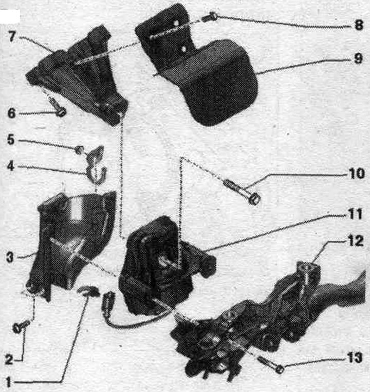


1. Holder: electrical plug connection.

1. Holder: electrical plug connection.
2. Bolt: 20 Nm.
3. Mounting plate: Engine mounts: If the engine mount is defective, replace the mounting plate; check the mounting plate on the opposite side and replace it if necessary.
4. Holder: hydraulic line.
5. Nut: 9 Nm.
6. Bolt: 40 Nm.
7. Engine mount: the image does not correspond to the version in the car.
8. Bolt: 10 Nm.
9. Thermal insulation: the image does not correspond to the version in the car.
10. Bolt: replace; 90 Nm + 90°.
11. Engine mount: only left with el. mag. electric valve. hydr., engine mounts "N144"; replace in pairs.
12. Subframe.
13. Bolt: 55 Nm.


Front support and crossmember
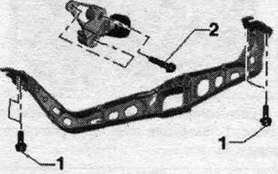


1. Bolt. 25 Nm. 2. Bolt. 40 Nm.

1. Bolt. 25 Nm. 2. Bolt. 40 Nm.


Removal and installation the engine mount


To avoid repeat repairs if there is a faulty engine mount, follow these steps. Replace the defective engine mount and the corresponding mounting shield. Also replace the engine mount on the opposite side, check the corresponding mounting bracket, replace if necessary. Remove the engine cover "arrows". Disconnect the plug connection "3". Unscrew the bolt "2" and release the hoses "1" from the holder. Place the differential pressure sensor "G505" back.
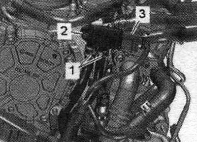
To avoid repeat repairs if there is a faulty engine mount, follow these steps. Replace the…


Release the "arrow" wire harness. Unscrew nuts "1" and remove holder "2".
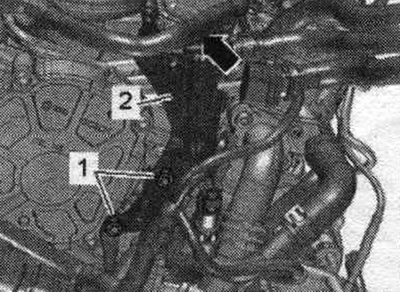
Release the «arrow» wire harness. Unscrew nuts «1» and remove holder «2».


Install the "10-222 A" crossmember on the shock absorber strut cups on the left and right, as shown in the figure. Attach the lead screws "10-222 A/11" to the engine suspension eyes. Apply pre-tension using the lead screws.
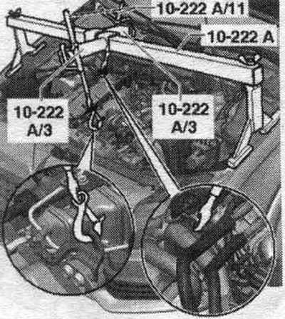


Install the «10-222 A» crossmember on the shock absorber strut cups on the left and right, as shown…


Remove the fender liner. Remove the front noise insulation "1". Unscrew the nut "2" and release the holder "1".
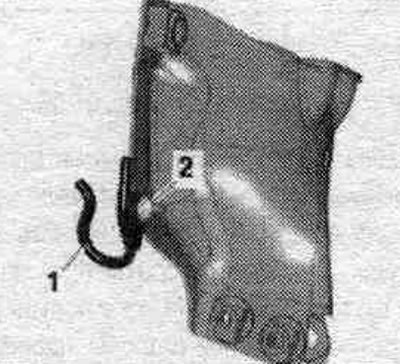
Remove the fender liner. Remove the front noise insulation «1». Unscrew the nut «2» and release the…


Release plug connection "3" of the solenoid valve. hydraulic engine mounts and disconnect it. Unscrew bolts "1, 4, 5" of the engine mount. Remove mounting plate "2" and engine mount.
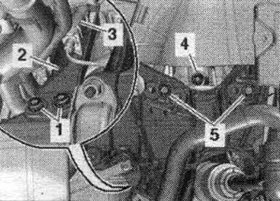
Release plug connection «3» of the solenoid valve. hydraulic engine mounts and disconnect it.…


Installation


Installation in reverse order. Replace bolts that were tightened with additional tightening. Install the fender liner and front sound insulation. Install the differential pressure sensor "G505".


Removal and installation the front support and crossmember


Remove the front noise insulation "1". Bring the lock mounting beam into the servo. position. Unscrew bolts "1" and remove the front engine mount. Unscrew the bolts on the left and right "2" and remove the cross member "3".
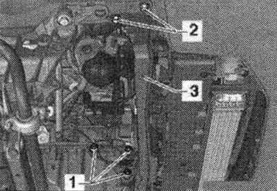
Remove the front noise insulation «1». Bring the lock mounting beam into the servo. position.…


Installation


Move the front mount "1" up to contact with the crossmember "arrow". In doing so, the buffer "2" must lie against the crossmember without gap or tension. In this position, tighten bolts "3".
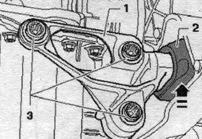
Move the front mount «1» up to contact with the crossmember «arrow». In doing so, the buffer «2»…


Installation in reverse order. Install the lock mounting beam. Install the front noise insulation screen.
The article was checked by auto expert Timur Bazhenov
This article is available at russian, bulgarian, belarusian, ukrainian, serbian, croatian, romanian, polish, slovak, hungarian

Share information:
Previous articles
Audi A4 B8: Diesel engines 2.0 l (CJCB)
Next articles

Engine installation
Removal the engine
Engine number and specifications
Cylinder block from the belt pulley side
Pistons and connecting rods — general information
Timing belt drive — removal, adjustment and installation
Cylinder head (CH) — removal and installation


Similar articles on other Audi car models:
Engine Mounting Brackets — Replacement Audi 80 B3 (1986-1991, petrol)
Cold Engine Idle Speed Adjustment Audi 100 C3 (1982-1990, diesel)
Starting the engine from an auxiliary power source Audi A3 Type 8L (1996-2003)
Engine compartment fastening and protection elements Audi A6 C5 Allroad (1999-2005)
Starting the engine Audi A8 D2 (1994-2002)
Gearbox removal — vehicles with 4-cylinder diesel engine Audi Q5 Type 8R (2008-2017)
Engine and gearbox mounting elements Audi A2 (1999-2005)
Link to this page in different formats


Visitor comments

No comments yet


How much will 16 + 20 =


A4(B8, 2007-2015) 
  • General information
  • Operating instructions
  • Power unit
  • Petrol engines 1.8 l
  • Petrol engines 1.8/2.0 l
  • Petrol engines 3.0 l
  • Petrol engines 3.2 l
  • Fuel system (petrol)
  • Diesel engines 2.0 l (CA*)
  • Diesel engines 2.0 l (CJCB)
  • Diesel engines 2.7/3.0 l
  • Diesel engines 3.0 l
  • Fuel system (diesel)
  • Transmission
  • Manual gearbox 0B1
  • Manual gearbox 0B2
  • Manual gearbox 0B3
  • Manual gearbox 0B4
  • Automatic transmission 0B5
  • Automatic transmission 0B6
  • Automatic transmission 0AW
  • All-wheel drive system
  • Chassis
  • Front suspension
  • Rear suspension
  • Brake system
  • Steering system
  • Body
  • Exterior
  • Interior
  • Seats
  • Doors, locks and windows
  • Security system
  • Heating and air conditioning
  • Electrical equipment
  • Audio system
  • Power devices
  • Equipment and devices
  • Lighting and lamps
  • Electrical circuits
 
A4(B7, 2004-2008) 
  • General information
  • Introduction to manual
  • Troubleshooting
  • Operating instructions
  • Maintenance
  • Power unit
  • Petrol engines 2.0 (ALT)
  • Petrol engines 2.0 (TFSI)
  • Petrol engines 1.8 (MPI)
  • Diesel engines
  • Cooling system
  • Air conditioner
  • Fuel and exhaust system
  • Ignition system
  • Starting and charging
  • Transmission
  • Clutch
  • Manual gearbox
  • Automatic gearbox
  • Drive shafts
  • Chassis
  • Brake system
  • Front suspension
  • Rear suspension
  • Steering
  • Body
  • Exterior
  • Interior
  • Electrical equipment
  • Equipment and devices
  • Lighting and signaling
  • Windscreen wipers and washers
  • Electrical diagrams
  • Electrical diagrams (since 2007)
 
A4(B6, 2000-2006) 
  • General information
  • Vehicle Description
  • User manual
  • Maintenance
  • Power unit
  • Gasoline engine
  • Diesel engine
  • Lubrication system
  • Cooling system
  • Supply system
  • Injection system
  • Exhaust system
  • Ignition and control
  • Transmission
  • Gear box
  • Clutch and drive shafts
  • Chassis
  • Brake system
  • Car suspension
  • Steering
  • Body
  • Heating and ventilation
  • Exterior (external elements)
  • Interior (internal elements)
  • Electrical equipment
  • Power devices
  • Lighting and appliances
  • Electrical circuits
 
A4(B6, 2000-2006, petrol) 
  • General information
  • Introduction to the guide
  • Car care
  • Power unit
  • Engine repair
  • Lubrication system
  • Cooling system
  • Injection and control system
  • Ignition system
  • Power and exhaust system
  • Transmission
  • Clutch and drive shafts
  • Car gearbox
  • Chassis
  • Suspension and wheels
  • Steering
  • Brake system
  • Body
  • Interior
  • Exterior
  • Electrical equipment
  • Equipment and devices
  • Lighting and signaling
  • Power devices
  • Electrical circuits
 
A4(B5, 1994-2001) 
  • General information
  • Introduction to the guide
  • Car care
  • Maintenance (gasoline)
  • Maintenance (diesel)
  • Power unit
  • Gasoline engines
  • Diesel engines
  • Engine overhaul
  • Cooling system
  • Fuel injection (gasoline)
  • Fuel system (diesel)
  • Exhaust system
  • Ignition system
  • Transmission
  • Clutch
  • Mechanical gearbox
  • Automatic gearbox
  • Drive shafts
  • Chassis
  • Brake system
  • Car suspension
  • Steering
  • Body
  • Exterior
  • Interior
  • Doors, locks and windows
  • Heating and ventilation
  • Electrical equipment
  • Power devices
  • Equipment and devices
  • Electrical circuits
 
A4(B5, 1994-2001, petrol) 
  • General information
  • Vehicle description
  • Maintenance
  • Power unit
  • Engine repair
  • Turbocharging
  • Exhaust system
  • Cooling system
  • Ignition system
  • Fuel system
  • Motronic injection system
  • MPI and MPFI injection system
  • Transmission
  • Clutch
  • Gearbox and shafts
  • Chassis
  • Steering
  • Car suspension
  • Brake system
  • Wheels and tires
  • Body
  • Heating and ventilation
  • Body parts
  • Electrical equipment
  • Fuses and relays
  • Power devices
  • Lighting and lamps
  • Tools and devices
  • Electrical circuits
 
AudiManual.ru © 2017-2026 · Mobile version · Feedback · Sitemap: EN BG BY UA RS HR RO PL SK HU · Site search · News and articles
80 B2 · 80 B3 petrol · 80 B3 · 80 B4 · 100 C3 diesel · 100 C3 petrol · 100 C3 · 100 C4 petrol · 100 C4 · A3 Type 8L · A4 B5 petrol · A4 B5 · A4 B6 petrol · A4 B6 · A4 B7 · A4 B8 · A6 C4 · A6 C5 · A6 C5 Allroad · A8 D2 · Q5 Type 8R · Q7 Typ 4L · Audi A2 ·
This site uses cookies 🍪. Click the button to accept this fact.