Repair Chevrolet Repair Toyota Repair Honda Repair AvtoVAZ Repair Mercedes-Benz Repair BMW Repair Opel
Home  |  Contacts  |  Sitemap  |    
English Русский
Български
Беларускі
Український
Српски
Hrvatski
Română
Polski
Slovenský
Magyar
AudiManual.ru


  • AUDI 80
  • AUDI 100
  • AUDI A3
  • AUDI A4
  • AUDI A6
  • AUDI A8
  • AUDI Q
  • OTHER
  • ARTICLES
B8 (2007-2015) B7 (2004-2008) B6 (2000-2006) B6 (2000-2006, petrol) B5 (1994-2001) B5 (1994-2001, petrol)

Timing belt drive — removal, adjustment and installation (Audi A4 B8)

  • Home
  • Audi A4
  • B8 (2007-2015)
  • Power unit
  • Diesel engines 2.0 l (CJCB)
  • Timing belt drive — removal, adjustment and installation
            0

Toothed belt drive


1. Timing belt: Before removing, mark the direction of rotation with chalk or a felt-tip pen; check…

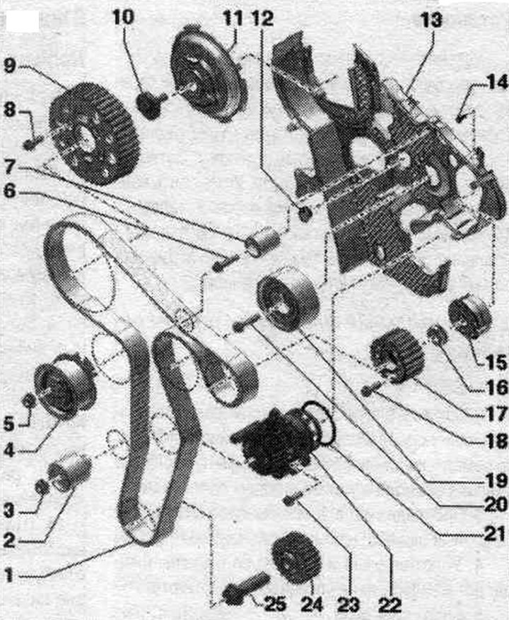
1. Timing belt: Before removing, mark the direction of rotation with chalk or a felt-tip pen; check for wear.
2. Intermediate roller.
3. Nut: 20 Nm.
4. Tension roller.
5. Nut: 20 Nm + 45°.
6. Bolt: 20 Nm.
7. Intermediate roller.
8. Bolt: 25 Nm.
9. Camshaft timing belt gear.
10. Bolt: loosening and tightening with counter support "T10051"; 100 Nm.
11. Camshaft hub.
12. Cork.
13. Rear timing belt guard.
14. Bolt: 9 Nm.
15. High pressure pump hub.
16. Nut.
17. High pressure pump toothed belt pulley.
18. Bolt.
19. Intermediate roller.
20. Bolt: replace; 50 Nm + 90°.
21. O-ring seal: Replace.
22. Coolant pump.
23. Bolt.
24. Crankshaft timing belt pulley: There should be no oil on the mating surfaces between the timing belt pulley and the crankshaft; installation is possible only in one position.
25. Bolt: replace; loosening and tightening with counter support "3415"; thread and flange add. do not lubricate; 120 Nm + 90°.


Removal


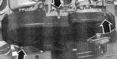
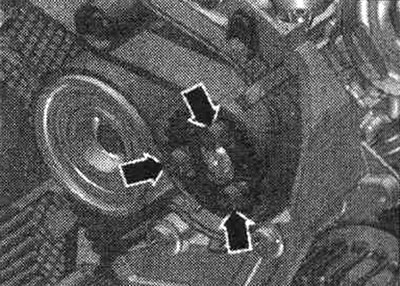
Remove the engine cover "arrows". Release the clips "arrows", remove the toothed belt protective cover. Remove the vibration damper.

Remove the engine cover «arrows». Release the clips «arrows», remove the toothed belt protective…


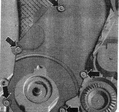
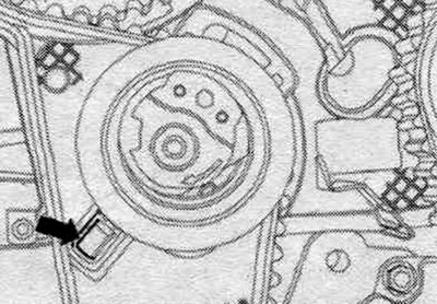
Unscrew the "arrow" bolts. Removing the lower timing belt cover.


Unscrew the «arrow» bolts. Removing the lower timing belt cover.


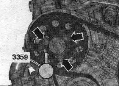
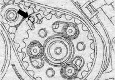
Risk of damage due to timing belt jumping. Turn the crankshaft only in the direction of engine rotation. Rotate the crankshaft using the timing belt bolt until the camshaft is at TDC. Secure the camshaft hub with the fuel pump locking pin. injection "3359". "Arrows" should not be taken into account.

Risk of damage due to timing belt jumping. Turn the crankshaft only in the direction of engine…


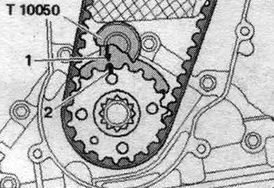
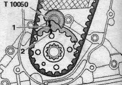
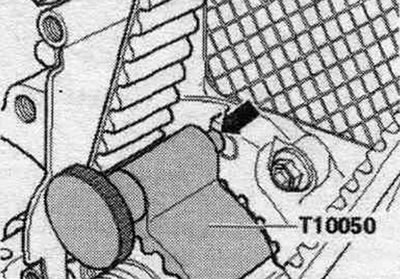
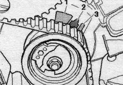
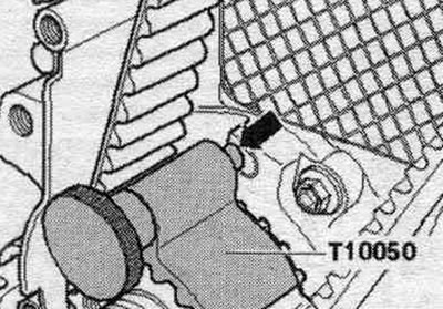
Lock the crankshaft toothed belt sprocket with the crankshaft stopper "T10050". The marks on the toothed belt pulley "2" and the crankshaft stopper "1" must be opposite each other "arrow". In doing so, the pin of the crankshaft retainer must engage in the hole of the seal. flange. The stopper can be pushed onto the sprocket only from the end face of the splines.

Lock the crankshaft toothed belt sprocket with the crankshaft stopper «T10050». The marks on the…


Loosen the camshaft timing belt sprocket arrow bolts by approximately 90°. Loosen the fuel pump timing belt pulley arrow bolts by approximately 90° using the XZN 10 "T10385" insert.


Loosen the camshaft timing belt sprocket arrow bolts by approximately 90°. Loosen the fuel pump…


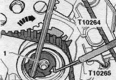
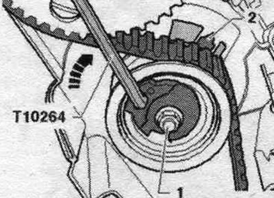
Loosen nut "1" of the tension roller. Turn the tension roller eccentric counterclockwise using the T10264 angle screwdriver so that the tension roller can be secured with the T10265 lock.

Loosen nut «1» of the tension roller. Turn the tension roller eccentric counterclockwise using the…


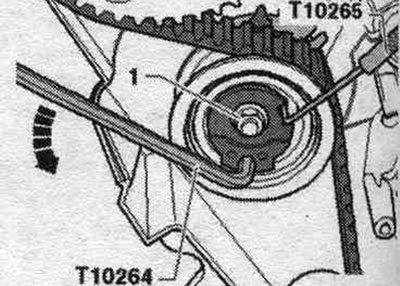
Then turn the tensioner roller eccentric with the angle screwdriver "T10264" clockwise "arrow" to the stop and tighten the nut "1" by hand. Remove the toothed belt first from the deflection roller, then from the remaining pulleys.

Then turn the tensioner roller eccentric with the angle screwdriver «T10264» clockwise «arrow» to…


Installation (timing adjustment)


To perform adjustment work on timing belts, the engine must be cold. Risk of damage to valves and piston crowns. When turning the camshaft, not a single piston of the crankshaft should be at "TDC".


Conditions: the tension roller is locked with the locking tool "T10265" and fixed "1" on the right stop: fix the camshaft hub with the locking pin of the system pump. injection "3359"; tighten the "arrow" bolts by hand; the camshaft timing belt gear should still rotate, but should not wobble; the crankshaft is fixed with the crankshaft stopper "T10050".

Conditions: the tension roller is locked with the locking tool «T10265» and fixed «1» on the right…


Secure the fuel injection pump hub using the fuel injection pump locking pin. injection "3359". Bolts "1" remain loosely screwed in. The high pressure pump timing belt gear should still rotate, but should not wobble.

Secure the fuel injection pump hub using the fuel injection pump locking pin. injection «3359».…


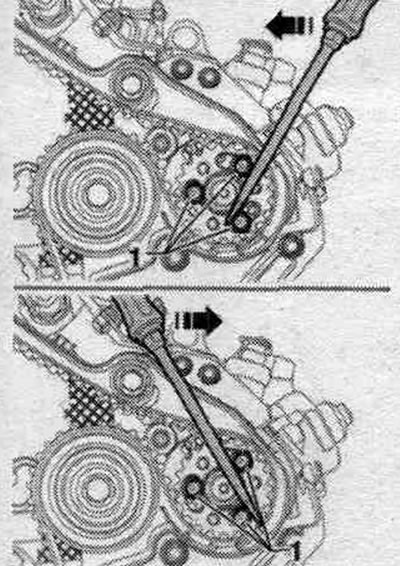
If necessary, rotate the high pressure pump toothed belt gear using the screwdriver "arrows" by the heads of the bolts "1" so that the hub can be locked with the locking pin.


If necessary, rotate the high pressure pump toothed belt gear using the screwdriver «arrows» by the…


Rotate the gears of the camshaft timing belt and the high-pressure pump in their longitudinal holes clockwise until they stop. Install the timing belt in the specified order.

1. Crankshaft timing belt pulley. 2. Tension roller. 3. Timing belt gear of the camshaft. 4. Gear…

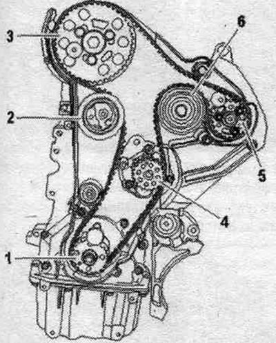
1. Crankshaft timing belt pulley. 2. Tension roller. 3. Timing belt gear of the camshaft. 4. Gear of the coolant pump toothed belt. 5. Pulley of the high-pressure pump toothed belt. 6. Intermediate roller.


Loosen nut "1" of the tension roller and remove locking pin "T10265". Ignore the "arrow".

Loosen nut «1» of the tension roller and remove locking pin «T10265». Ignore the «arrow».


Pay attention to the proper fit of the tension roller in the rear timing belt housing "arrow".


Pay attention to the proper fit of the tension roller in the rear timing belt housing «arrow».


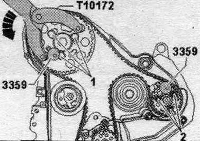
Install the counter support "T10172" on the camshaft timing belt sprocket as shown in the figure. Turn the counter-support counterclockwise "arrow" and hold it under pre-tension. In this position, tighten the bolts "1" of the camshaft toothed belt sprocket and the bolts "2" of the high-pressure pump toothed belt sprocket. Tightening torque 20 Nm.

Install the counter support «T10172» on the camshaft timing belt sprocket as shown in the figure.…


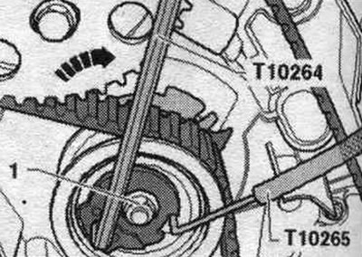
Now carefully rotate the tension roller eccentric using the T10264 angle screwdriver in the clockwise direction until the pointer "2" is opposite the recess in the support plate. Nut "1" must not be turned. Hold the tension roller in this position and tighten the nut. Remove locking pin "3359" and crankshaft stop "T10050".

Now carefully rotate the tension roller eccentric using the T10264 angle screwdriver in the…


Checking the timing phases


Turn the crankshaft only in the direction of engine rotation. Rotate the crankshaft using the timing belt bolt 2 turns in the direction of engine rotation until the crankshaft is again close to TDC. Reinsert the T10050 crankshaft stopper into the crankshaft timing belt sprocket. Rotate the crankshaft in the direction of engine rotation until. until the crankshaft stop pin "arrow" is fixed in the seal during rotation. flange.


Turn the crankshaft only in the direction of engine rotation. Rotate the crankshaft using the…


The camshaft hub must be secured with the fuel pump locking pin. injection "3359". "Arrows" should not be taken into account. The high pressure pump hub fixing point can be very difficult to locate. However, a slight deviation of the "arrow" will not affect the engine's operation.

The camshaft hub must be secured with the fuel pump locking pin. injection «3359». «Arrows» should…


The tension roller pointer "2" should be located in the middle between the tongues "1" and "3" of the support plate. Lateral displacement is allowed to be maximum 5 mm.

The tension roller pointer «2» should be located in the middle between the tongues «1» and «3» of…


If the conditions are not met, adjust the timing. If the conditions are met, continue with the timing adjusted correctly.


Timing phase correction


If you cannot lock the camshaft hub, remove the crankshaft stopper "T10050" enough so that the journal opens access to the hole. Turn the crankshaft counterclockwise slightly past TDC. Slowly turn the crankshaft in the direction of engine rotation until the camshaft hub can be locked. After fixing, loosen the camshaft timing belt gear bolts. The journal A of the crankshaft stopper "T10050" is located to the left of the hole: rotate the crankshaft in the direction of engine rotation until the journal "arrow" of the crankshaft stopper is fixed in the seal during rotation. flange. Tighten the camshaft timing belt sprocket bolts to 20 Nm.

If you cannot lock the camshaft hub, remove the crankshaft stopper «T10050» enough so that the…


The journal B of the crankshaft stop "T10050" is located to the right of the hole: first turn the crankshaft slightly against the direction of engine rotation; rotate the crankshaft again in the direction of engine rotation until the crankshaft stop journal engages in the seal during rotation. flange. Tighten the camshaft timing belt sprocket bolts to 20 Nm.

Continued with correctly adjusted timing phases


Remove the system pump lock pin. injection valve "3359" and crankshaft lock "T10050". Rotate the crankshaft by the timing belt bolt 2 turns in the direction of engine rotation until the crankshaft is again close to "TDC". Repeat the timing belt phase check. If the camshaft hub can now be locked, tighten bolts "1" of the camshaft timing belt sprocket to the specified torque. Tighten bolts "2" of the high-pressure pump toothed belt gear to the specified torque. Repeat the timing phase check.

Install


Installation in reverse order. Replace seals. Secure all hose connections with hose clamps of the appropriate series. Install the vibration damper.
The article was checked by auto expert Timur Bazhenov
This article is available at russian, bulgarian, belarusian, ukrainian, serbian, croatian, romanian, polish, slovak, hungarian

Share information:
Previous articles
Audi A4 B8: Diesel engines 2.0 l (CJCB)
Next articles

Pistons and connecting rods — general information
Cylinder block from the belt pulley side
Engine and gearbox mounting elements — removal and installation
Engine installation
Cylinder head (CH) — removal and installation
Valve mechanism — removal and installation
Lubrication system — replacement of pump and balance shafts
Lubrication System — Oil Filter Holder and Oil Cooler


Similar articles on other Audi car models:
Generator drive belt — removal, installation and adjustment Audi 80 B3 (1986-1991, petrol)
Air Conditioner Drive Belt — Removal, Installation and Adjustment Audi 100 C3 (1982-1990, diesel)
Removal, installation and tensioning the timing belt (petrol) Audi A3 Type 8L (1996-2003)
Removal and installation the timing belt — Diesel engine… Audi A6 C5 (1997-2004)
Removal and installation the outer joint of the drive shaft Audi A8 D2 (1994-2002)
Removal and installation the fuel injection pump drive belt Audi Q7 Typ 4L (2005-2015, diesel)
Removal and installation the crankshaft belt drive pulley Audi A2 (1999-2005)
Link to this page in different formats


Visitor comments

No comments yet


How much will 24 + 20 =


A4(B8, 2007-2015) 
  • General information
  • Operating instructions
  • Power unit
  • Petrol engines 1.8 l
  • Petrol engines 1.8/2.0 l
  • Petrol engines 3.0 l
  • Petrol engines 3.2 l
  • Fuel system (petrol)
  • Diesel engines 2.0 l (CA*)
  • Diesel engines 2.0 l (CJCB)
  • Diesel engines 2.7/3.0 l
  • Diesel engines 3.0 l
  • Fuel system (diesel)
  • Transmission
  • Manual gearbox 0B1
  • Manual gearbox 0B2
  • Manual gearbox 0B3
  • Manual gearbox 0B4
  • Automatic transmission 0B5
  • Automatic transmission 0B6
  • Automatic transmission 0AW
  • All-wheel drive system
  • Chassis
  • Front suspension
  • Rear suspension
  • Brake system
  • Steering system
  • Body
  • Exterior
  • Interior
  • Seats
  • Doors, locks and windows
  • Security system
  • Heating and air conditioning
  • Electrical equipment
  • Audio system
  • Power devices
  • Equipment and devices
  • Lighting and lamps
  • Electrical circuits
 
A4(B7, 2004-2008) 
  • General information
  • Introduction to manual
  • Troubleshooting
  • Operating instructions
  • Maintenance
  • Power unit
  • Petrol engines 2.0 (ALT)
  • Petrol engines 2.0 (TFSI)
  • Petrol engines 1.8 (MPI)
  • Diesel engines
  • Cooling system
  • Air conditioner
  • Fuel and exhaust system
  • Ignition system
  • Starting and charging
  • Transmission
  • Clutch
  • Manual gearbox
  • Automatic gearbox
  • Drive shafts
  • Chassis
  • Brake system
  • Front suspension
  • Rear suspension
  • Steering
  • Body
  • Exterior
  • Interior
  • Electrical equipment
  • Equipment and devices
  • Lighting and signaling
  • Windscreen wipers and washers
  • Electrical diagrams
  • Electrical diagrams (since 2007)
 
A4(B6, 2000-2006) 
  • General information
  • Vehicle Description
  • User manual
  • Maintenance
  • Power unit
  • Gasoline engine
  • Diesel engine
  • Lubrication system
  • Cooling system
  • Supply system
  • Injection system
  • Exhaust system
  • Ignition and control
  • Transmission
  • Gear box
  • Clutch and drive shafts
  • Chassis
  • Brake system
  • Car suspension
  • Steering
  • Body
  • Heating and ventilation
  • Exterior (external elements)
  • Interior (internal elements)
  • Electrical equipment
  • Power devices
  • Lighting and appliances
  • Electrical circuits
 
A4(B6, 2000-2006, petrol) 
  • General information
  • Introduction to the guide
  • Car care
  • Power unit
  • Engine repair
  • Lubrication system
  • Cooling system
  • Injection and control system
  • Ignition system
  • Power and exhaust system
  • Transmission
  • Clutch and drive shafts
  • Car gearbox
  • Chassis
  • Suspension and wheels
  • Steering
  • Brake system
  • Body
  • Interior
  • Exterior
  • Electrical equipment
  • Equipment and devices
  • Lighting and signaling
  • Power devices
  • Electrical circuits
 
A4(B5, 1994-2001) 
  • General information
  • Introduction to the guide
  • Car care
  • Maintenance (gasoline)
  • Maintenance (diesel)
  • Power unit
  • Gasoline engines
  • Diesel engines
  • Engine overhaul
  • Cooling system
  • Fuel injection (gasoline)
  • Fuel system (diesel)
  • Exhaust system
  • Ignition system
  • Transmission
  • Clutch
  • Mechanical gearbox
  • Automatic gearbox
  • Drive shafts
  • Chassis
  • Brake system
  • Car suspension
  • Steering
  • Body
  • Exterior
  • Interior
  • Doors, locks and windows
  • Heating and ventilation
  • Electrical equipment
  • Power devices
  • Equipment and devices
  • Electrical circuits
 
A4(B5, 1994-2001, petrol) 
  • General information
  • Vehicle description
  • Maintenance
  • Power unit
  • Engine repair
  • Turbocharging
  • Exhaust system
  • Cooling system
  • Ignition system
  • Fuel system
  • Motronic injection system
  • MPI and MPFI injection system
  • Transmission
  • Clutch
  • Gearbox and shafts
  • Chassis
  • Steering
  • Car suspension
  • Brake system
  • Wheels and tires
  • Body
  • Heating and ventilation
  • Body parts
  • Electrical equipment
  • Fuses and relays
  • Power devices
  • Lighting and lamps
  • Tools and devices
  • Electrical circuits
 
AudiManual.ru © 2017-2026 · Mobile version · Feedback · Sitemap: EN BG BY UA RS HR RO PL SK HU · Site search · News and articles
80 B2 · 80 B3 petrol · 80 B3 · 80 B4 · 100 C3 diesel · 100 C3 petrol · 100 C3 · 100 C4 petrol · 100 C4 · A3 Type 8L · A4 B5 petrol · A4 B5 · A4 B6 petrol · A4 B6 · A4 B7 · A4 B8 · A6 C4 · A6 C5 · A6 C5 Allroad · A8 D2 · Q5 Type 8R · Q7 Typ 4L · Audi A2 ·
This site uses cookies 🍪. Click the button to accept this fact.