
Cylinder head cover
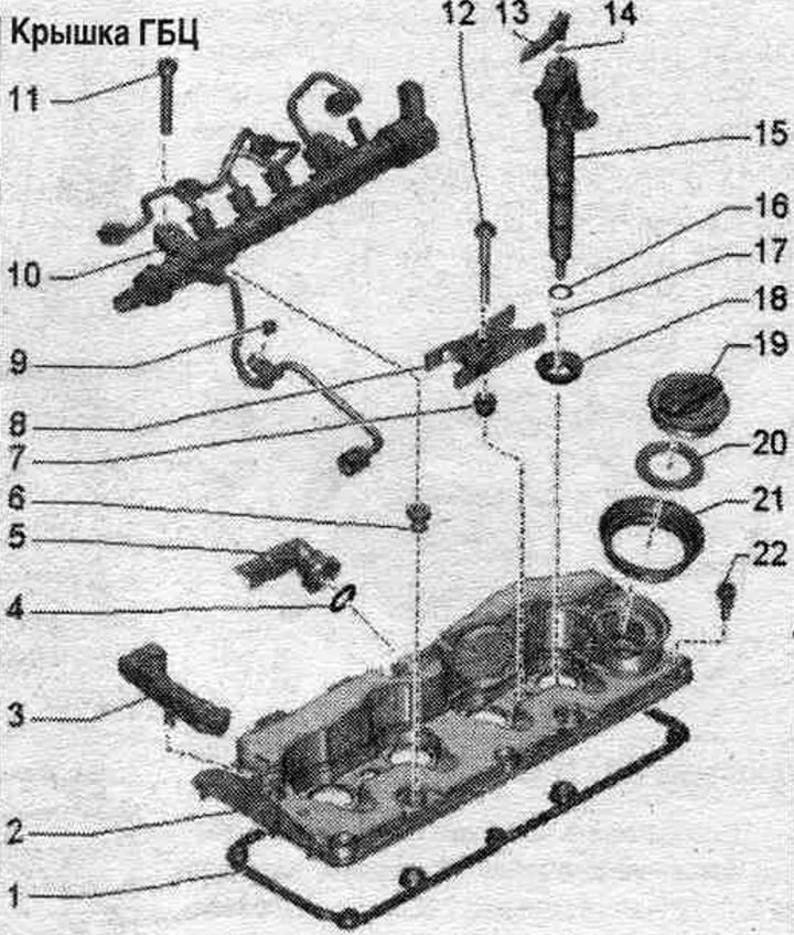
1. Gasket: replace if damaged or leaking.
2. Cylinder head cover.
3. Holder: for vacuum lines and wires.
4. O-ring seal: Replace; replace.
5. Hose: crankcase ventilation; to remove, press the release buttons.
6. Fuel distributor sealing sleeve: replace if damaged or leaking.
7. Nozzle.
8. Clamp.
9. Bolt.
10. Fuel distributor; do not change the bend of high pressure pipelines.
11/12. Bolt.
13. Reverse fuel. highway.
14. O-ring seal: Replace.
15. Nozzle.
16. O-ring seal: Replace.
17. Copper seal. ring: replace.
18. Injector sealing cuff; replace.
19. Lid.
20. Lid gasket.
21. Nozzle.
22. Bolt: replace if seal is damaged.
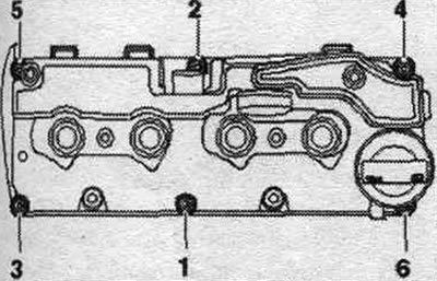
Cylinder head cover - torque and sequence, tightening
Tighten the cylinder head cover bolts in sequence. "1...6" with a torque of 9 Nm. Ensure that there is no distortion in the position of the cylinder head cover.
Removal
Remove the system unit. injection.
Remove the fuel distributor.
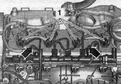
Release the arrow clamps and remove the timing belt protective cover.
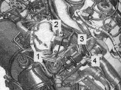
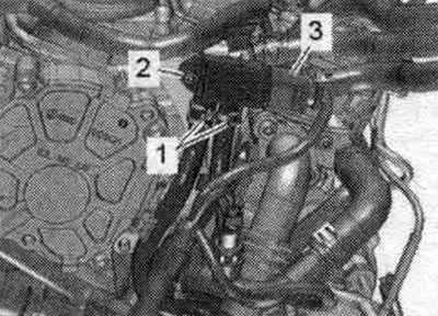
Disconnect plug connections "2, 3, 4". Release the wires. Remove and release vacuum hose "1".
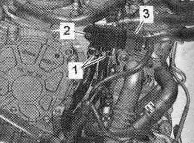
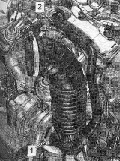
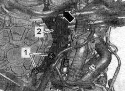
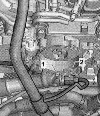
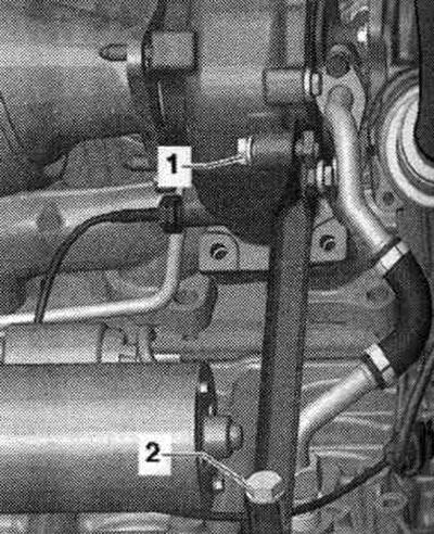
Unscrew bolt "2" and release hose "1" on the bracket. Place the differential pressure sensor "G505" back.
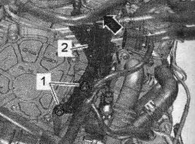
Release the "arrow" wiring harness. Unscrew nuts "1" and remove holder "2".
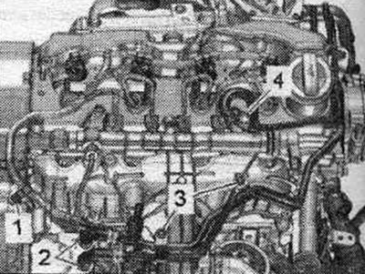
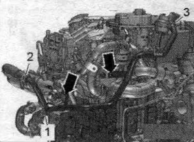
Unscrew bolts "1, 3". Remove fuel hoses by loosening hose clamps "2". Pull back fuel. lines from the cylinder head cover up and push them to the side. "Pos. 4" should not be taken into account.
Disconnect the crankcase ventilation hose "2" by pressing the release buttons. "Pos. 1" should not be taken into account.
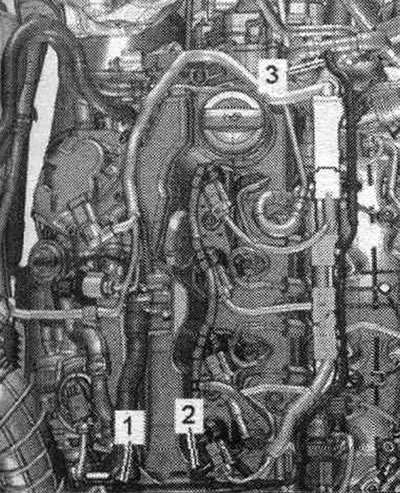
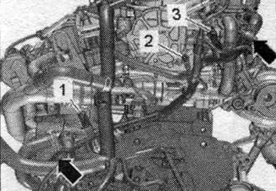
Remove vacuum hose "2". Remove cylinder head cover holder "1" and set aside. "Pos. 3" should not be taken into account.
Loosen the cylinder head cover bolts in sequence. "6...1" and unscrew them.
Installation
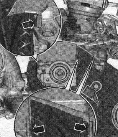
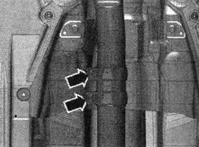
Installation in reverse order. Replace the seal. o-ring. Secure all hose connections with hose clamps of the appropriate series. If damaged or leaking, replace the cylinder head cover gasket and bolts. Replace the nozzles and seals. injector rings if damaged or leaking. Tighten the cylinder head cover bolts. Make sure that the cylinder head cover is correctly snapped into the toothed belt cover "arrows". For clarity, the assembly. the position is shown with the camshaft gear removed.
Check the clearance between the hub and the timing belt cover. Install the fuel distributor and injection nozzles. Electrical connections and wiring. Remove air from fuel. syst..
Cylinder head
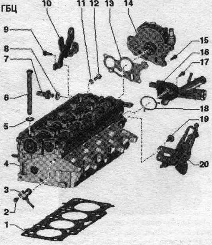
1. Cylinder head seal: replace; after replacement, replace the coolant and oil.
2. Bolt: insert with threaded varnish; 10 Nm.
3. Hall sensor "G40": for camshaft position.
4. Cylinder head: Place the removed cylinder head on a foam pad, otherwise damage may occur. Glow plugs: Do not process; before installation, check the presence of 2 oil centering bushings. pump and cylinder block; after replacement, replace the coolant and oil.
5. Washer.
6. Bolt: replace; take into account the aftereffects when turning away.
7. Oil pressure sensor "F1": switching pressure 0.3...0.6 bar; check; 20 Nm.
8. Sealing cuff: replace.
9. Bolt: 20 Nm.
10. Engine suspension eye.
11. Sealing cuff: replace.
12. Threaded plug: 20 Nm.
13. Gasket: replace.
14. Vacuum pump.
15. Bolt.
16. Connecting pipe of system hoses. cooling: with coolant temperature sensor "G62"; the image does not correspond to the version in the car.
17. Bolt.
18. Gasket: replace.
19. Bolt: 20 Nm.
20. Engine suspension eye.
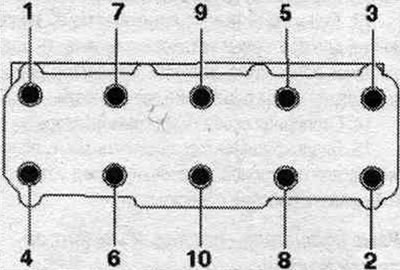
Cylinder head - bolt tightening sequence and torque
Replace bolts that were tightened with additional tightening.
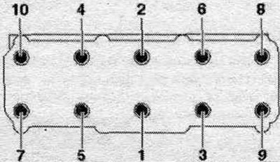
Tighten the bolts in 4 stages in the sequence shown.
| Stage | Bolts | Tightening torque/rotation angle |
| 1 | "1...10" | 30 Nm |
| 2 | "1...10" | 50 Nm |
| 3 | "1...10" | turn 90° |
| 4 | "1...10" | turn 90° |
Cylinder head gasket markings
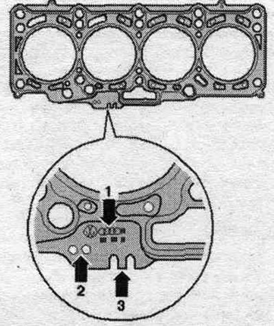
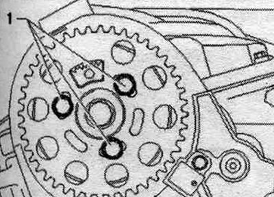
1. Part number. 2. Holes. 3. Not taken into account.
Note: The thickness of the cylinder head gasket to be installed depends on the piston protrusion. If only the cylinder head gasket is replaced, a new gasket with the same designation should be used. that and the old one.
Removal and installation the cylinder head
Remove the front wall of the water drainage box. Remove the air casing. filter. Remove the timing belt. Remove the left, upper coolant pipe.
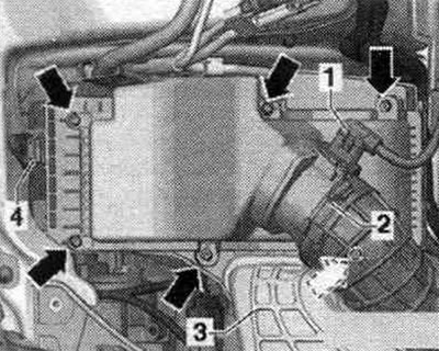
Disconnect plug connection "3" of differential pressure sensor "G505". Unscrew bolt "2" and release hoses "1" from the holder. Place the differential pressure sensor "G505" back.
Release the "arrow" wire harness. Unscrew nuts "1" and remove holder "2".
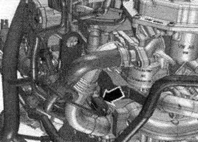
Unscrew the bolt and nut "arrows". Remove the coolant hose by loosening the hose clamp "3". The rear right pipe of the system. cooling press aside. "Pos. 1, 2" do not take into account.
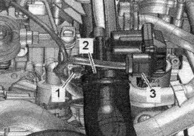
Disconnect plug connection "3". Unscrew bolt "1". Remove the coolant hoses from the coolant pipe by loosening the hose clamps "arrows". Set the differential pressure sensor back. "Pos. 2" should not be taken into account.
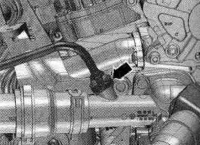
Disconnect plug connection "2" of coolant temperature sensor "G62". Ignore "Pos. 1".
Disconnect the "arrow" plug connection of the "F1" oil pressure sensor.
Unscrew bolt "1" of the oil dipstick guide tube. Disconnect plug connection "3" of the throttle valve control unit "J338". Ignore "Pos. 2".
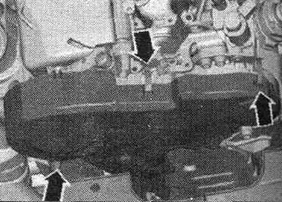
Remove the cylinder head cover. Remove the system line. cooling, for which purpose loosen the "arrow" fastening brackets.
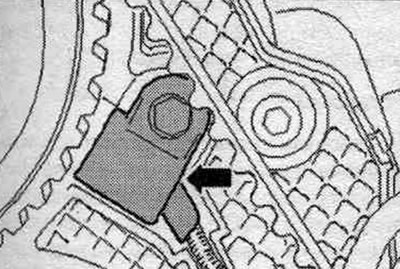
Loosen turbocharger bolt "1". "Pos. 2" should not be taken into account.
Loosen the "arrow" clamping sleeve.
Unscrew the turbocharger arrow nuts. "Pos. 1, 2" do not take into account. Release the wire harness on the cylinder head.
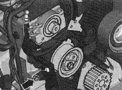
Unscrew bolts "1" and remove the camshaft timing belt gear.
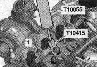
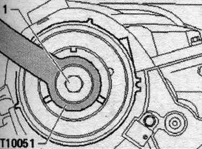
Loosen bolt "1" of the camshaft hub, holding it in place with counterstop "T10051." Loosen the bolt approximately 2 turns.
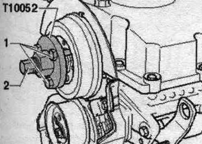
Place the puller "T10052" on the camshaft hub and screw bolts "1" into the hub. To remove the camshaft hub, screw in bolt "2" and hold it by the Allen key (30mm) of the puller. Remove the hub from the camshaft cone.
Unscrew the bolt "arrow" of the rear timing belt cover.
Unscrew the "G40" Hall sensor bolt "arrow", put the "G40" Hall sensor aside.
Loosen the cylinder head bolts in sequence. "1...10". Two mechanics are required to remove the cylinder head. Remove the timing belt tensioner roller when removing the cylinder head from the locating pin.
Release the cylinder head back from the rear casing - toothed belt and at the same time remove the tension roller. Be careful not to damage the turbocharger oil drain line. Place the cylinder head so as not to bend the oil drain line. If necessary, place a wooden block under the exhaust manifold. Risk of damage to glow plug stems during cylinder head installation. Do not place a removed cylinder head with glow plugs installed on the mating surface, as the glow plug stems protrude slightly beyond the mating surface.
In vehicles with a 2.0 4V Common Rail TDI engine, only steel glow plugs are installed.
Installation
Caution! Risk of damage to the sealing surface. Carefully remove any remaining sealant from the cylinder head and cylinder block. Avoid creating long scratches or burrs. Risk of damage to the cylinder block. The blind holes of the cylinder head mounting bolts should be free of oil or coolant. During repairs, carefully remove any remaining sealant from the cylinder head and cylinder block. Avoid creating long scratches or burrs. Carefully remove any residue left after sanding and grinding. The new cylinder head seal should be removed from the packaging immediately before installation. To prevent damage to the silicone layer and the grooves of the cylinder head gasket, handle the gasket with particular care. Risk of damage to open valves. When installing a replacement cylinder head, remove the plastic base to protect the exposed valves only when it comes into direct contact with the cylinder head. There is a risk of damage to the valves and piston crowns after working on the valve train. To ensure that no valves are touching the cylinder head during operation, carefully rotate the crankshaft at least 2 revolutions. Replace any bolts that were overtightened. Replace self-locking nuts, lip seals, gaskets and seals. rings. Modification of cylinder heads of TDI engines is prohibited. If a cylinder head from the exchange stock is installed, the contact surfaces between the rocker arm and the camshaft bearing housing should be lubricated. Secure all hose connections with hose clamps of the appropriate series. After replacing the cylinder head or cylinder head gasket, it is necessary to completely replace the coolant and oil.
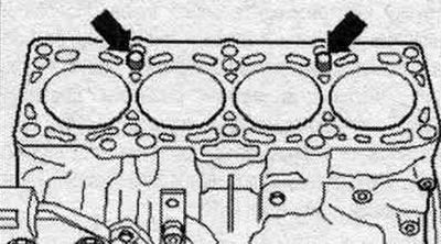
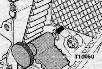
Before installing the cylinder head, remove the crankshaft stop "T10050" and rotate the crankshaft counterclockwise until all pistons are evenly positioned below TDC. If the cylinder block does not have centering bushings for aligning the cylinder block and cylinder head, they must be installed. Take into account the markings on the cylinder head gasket.
1. Part number. 2. Holes. 3. Not taken into account.
Note: After replacing the cylinder head gasket or cylinder head, select a new cylinder head gasket according to the number of holes in the old gasket. If the crank mechanism components have been replaced, then the new cylinder head gasket should be selected according to the measurements of the piston protrusion at the TDC position.
Place the cylinder head gasket on the centering bushings "arrows" in the cylinder block. Cylinder head gasket installation position: marked "top" or cylinder head part number.
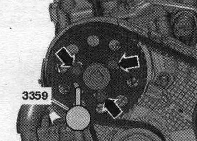
Insert the cylinder head with the pin bolt of the timing belt tension roller into the recess of the timing belt protective cover at the rear and simultaneously fit the tension roller. Ensure the correct wiring to the G40 Hall sensor is routed. Install the cylinder head. Install the cylinder head bolts and tighten them hand-tight until they stop. Tighten the cylinder head bolts. Install the rear timing belt cover, hub, and camshaft timing belt sprocket. Secure the camshaft hub with the fuel pump locking pin. injection "3359". "Arrows" should not be taken into account.
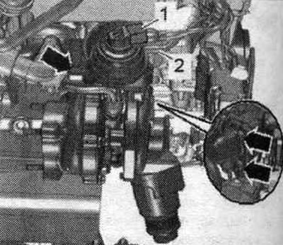
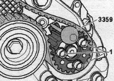
Secure the high pressure pump hub with the high pressure pump locking pin. injection "3359". "Pos. 1" should not be taken into account.
Rotate the crankshaft in the direction of engine rotation until the "arrow" pin of the crankshaft stop "T10050" enters the seal during rotation. flange. Install the timing belt (adjust the timing phases).
Installation in reverse order. Install the cylinder head cover. Install the poly V-belt. Install the rear coolant pipe. Install the turbocharger. Electrical connections and wiring. Install the dipstick guide tube. Connect the air duct hoses using threaded clamps. Install the rear right coolant pipe. Install the differential pressure sensor "G505". Install the upper left coolant pipe. Install the air intake housing. filter. Install the front wall of the water drainage box. Change the oil. Replace the coolant.
[The text is based on materials from the website: AUDImanual.ru]