
Table of contents: Valve mechanism ↓ Crankshaft frame - last and bolt… ↓ Removal and installation camshafts ↓
Valve mechanism
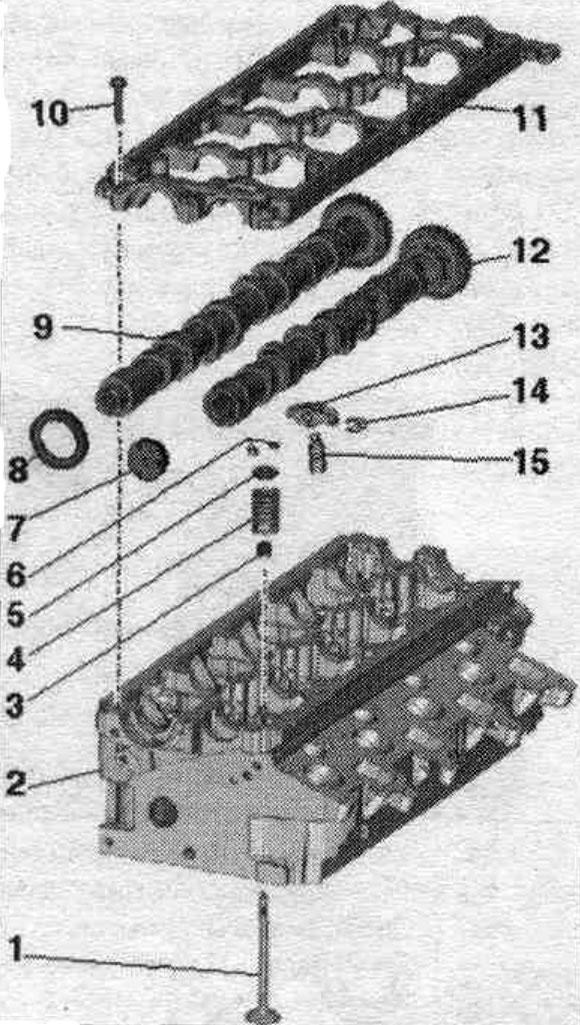
1. Valve: cannot be machined, only lapping is allowed; mark mont. reinstallation position.
2. Cylinder head.
3. Valve stem seal.
4. Valve spring.
5. Valve spring plate.
6. Valve cracker.
7. Lid: replace; removal: With the camshaft frame installed, use an awl to pry the cover from one side and remove it; installation: Press in without sealant using a suitable mandrel; pressing depth 1...2 mm.
8. Shaft gasket.
9. Exhaust camshaft.
10. Bolt: take into account the sequence when unscrewing.
11. Camshaft frame: with integrated camshaft bearings.
12. Intake camshaft.
13. Roller lever: mark mounting. reinstallation position; check the roller bearings for ease of rotation; before installation, lubricate the working surfaces.
14. Hydraulic compensator locking bracket.
15. Hydraulic compensator: mark installation. reinstallation position; before installation, lubricate the working surfaces.
Crankshaft frame - last and bolt tightening torque
Tighten the bolts in 2 stages in the sequence shown.
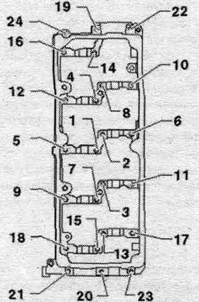
| Stage | Bolts | Tightening torque |
| 1 | "1...24" | Screw in by hand until it stops. The bearing frame must fit snugly against the cylinder head over the entire contact surface |
| 2 | "1...24" | 10 Nm |
Removal and installation camshafts
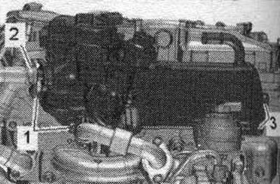
The cylinder head is installed. Remove the engine cover "arrows". Remove the toothed belt from the camshaft toothed belt pulley and the high-pressure pump toothed belt pulley. Remove the air casing. filter. Disconnect the engine crankcase ventilation hose "2" by pressing the release buttons. Remove the air duct hose by loosening the hose clamp "1". Remove the cylinder head cover.

Unscrew bolts "1, 3", system radiator. eGR leave in mont. position.
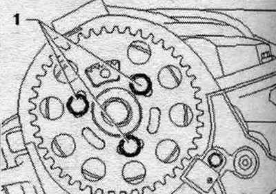
Unscrew bolts "1" and remove the camshaft timing belt gear.
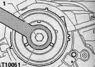
Loosen bolt "1" of the camshaft hub, holding it in place with counterstop "T10051." Loosen the bolt approximately 2 turns.
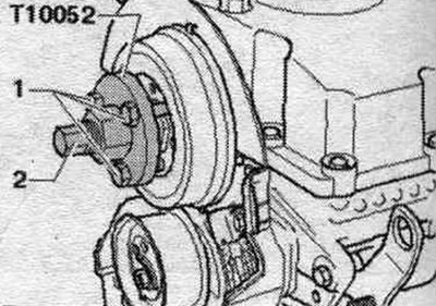
If the hub cannot be removed by hand: place the "T10052" puller on the camshaft hub and screw bolts "1" into the hub. To remove the camshaft hub, screw in bolt "2" and hold it by the Allen key (30mm) of the puller. Remove the hub from the camshaft cone. Remove the vacuum pump.
Loosen the camshaft frame bolts in sequence. "24...1". Unscrew the bolts and carefully peel off the camshaft frame. Mark for reinstallation and remove the camshafts.
Installation
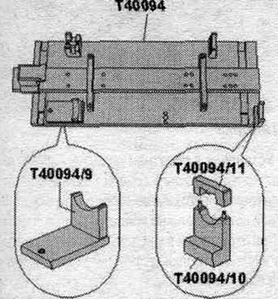
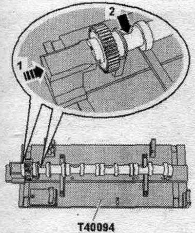
Risk of damage to the thrust bearing in the frame. Camshafts should only be installed using the T40094- camshaft installation tool as described below. Risk of contamination of the system. lubricants and bearings. Cover open engine parts. Remove any remaining sealant from the cylinder head and support frame, for example, using a rotating brush attachment with plastic bristles. Clean the sealing surfaces from oil and grease. Lubricate the working surface of the camshafts with oil. Equip the camshaft installation tool "T40094" as follows: screw the supports "T40094/9" and "T40094/10" (with "T40094/11") onto the main plate, as shown in the figure. If necessary, remove the screwed supports in this place.
Install support "T40094/1" to position "F" and support "T40094/2" to position "A".
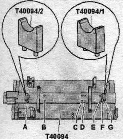
Place the intake camshaft on the supports "T40094/1" and "T40094/2". Turn the intake camshaft so that it can be locked with the retainer in the "TDC" position "arrow 1". The concavity "arrow 2" of the cylinder head bolt must face outwards.
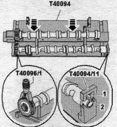
Place the exhaust camshaft on supports "T40094/9" and "T40094/10". Secure the exhaust camshaft with cover "T40094/11". Protrusion "1" of the cover must fit into groove "2" in the camshaft. Install the clamping tool "T40096/1" on the gear engagement of the exhaust camshaft so that each neck of the clamping tool engages on each half of the gear. The wide neck should fit into the wide half of the gear. Tighten the clamping device with the knurled wheel until the tooth profiles are level. Push the intake camshaft towards the exhaust camshaft until their teeth engage in the "arrow" pattern.
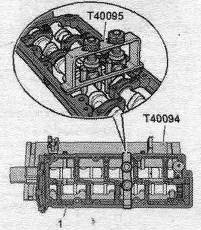
Install the frame onto the camshafts. All camshaft bearings must be located on the camshafts. Install the camshaft frame "T40095" and secure the camshafts in the frame as shown in the figure. Remove the cap "T40094/11". Observe the expiration date of the sealant.
Cut off the tube tip along the front mark (opening diameter approx. 2 mm). Risk of contamination of camshaft bearings due to excess sealant. The sealant strips must not be thicker than the specified size. Apply a bead of sealant to the clean cylinder head seating surfaces as shown in the figure.
Sealant bead thickness: 2...3 mm. Install and tighten the camshaft frame immediately, as the sealant begins to harden immediately. After installing the frame, allow the sealant to harden for about 30 minutes.
Remove the camshafts together with the frame, the "T40095" camshaft stand, and the "T40096/1" clamping tool from the "T40094" camshaft stand and carefully insert them into the cylinder head. Screw in the camshaft frame bolts in sequence. "1...24" evenly from hand to stop. The frame must fit snugly against the cylinder head over the entire mating surface. Tighten the bolts. Remove the camshaft installation tool "T40095" and the clamping device "T40096/1". Installation is in reverse order. Install the camshaft oil seal. Press the new cover into the cylinder head using a suitable mandrel to a depth of 1...2 mm. Install the vacuum pump. Install the cylinder head cover.