
Table of contents: Oil sump, oil pump, balance shaft… ↓ Oil pan - last and tightening torque ↓ Removal and installation of oil. pump ↓ Removal the balance shaft module ↓
Oil sump, oil pump, balance shaft block
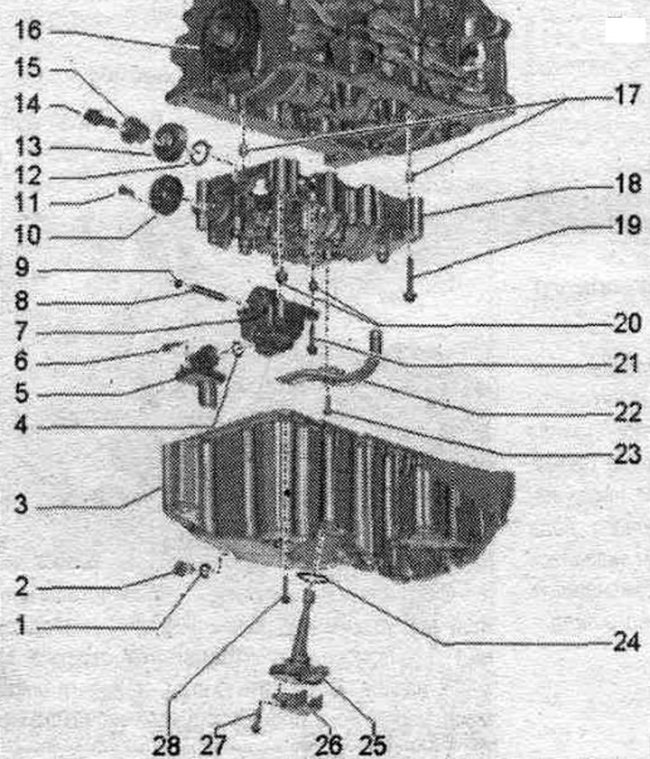
1. Sealing cuff: replace.
2. Oil drain plug: 30 Nm.
3. Oil pan.
4. Bolt: 9 Nm.
5. Suction line: if dirty, clean the mesh filter.
6. O-ring seal: Replace.
7. Oil pump: Before installation, check that both installation bushings for centering the balance shaft module on the cylinder block are in place.
8. Drive shaft oil. pump.
9. Retaining ring: should fit at the base of the groove; a damaged or overtightened retaining ring must be replaced.
10. Cylindrical gear of the balance shaft.
11. Bolt: replace; 20 Nm + 90°.
12. Intermediate gear thrust bearing washer; replace; to install the intermediate gear, secure it to the balance shaft module with grease.
13. Intermediate gear: replace: to achieve the correct tooth profile clearance, the new intermediate gear has a coating that, through wear, ensures the correct clearance; mounting position: Part number must be visible; pay attention to the correct fit of the thrust bearing washer.
14. Bolt: with washer; replace; 90 Nm + 90°.
15. Intermediate gear hub; replace.
16. Crankshaft gear.
17. Centering bushings.
18. Balance shaft block: Before installation, check that both installation bushings for centering the balance shaft block on the cylinder block are in place.
19. Bolt: replace.
20. Centering bushings.
21. Bolt: 9 Nm.
22. Oil intake pipe.
23. Bolt: 9 Nm.
24. Sealing cuff: replace.
25. Oil level and temperature sensor "G266".
26. Cover of oil level and temperature sensor "G266".
27. Bolt: self-locking; replace; 9 Nm.
28. Bolt: replace.
Oil pan - last and tightening torque
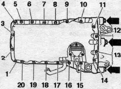
Tighten the bolts in 3 stages.
| Stage | Bolts | Tightening torque |
| 1 | "1...20" | crosswise 5 Nm |
| 2 | "arrows" | 40 Nm |
| 3 | "1...20" | tighten in stages crosswise with a final tightening torque of 13 Nm |
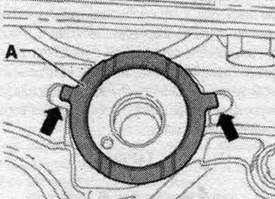
Mounting position of thrust bearing washer
Caution! Risk of thrust bearing washer slipping behind the intermediate gear. Make sure that the thrust bearing washer "A" does not slip out through the unevenness of the balance shaft module housing "arrow" when installing the intermediate gear and thus subsequently become jammed. If necessary, secure with grease to the balance shaft module housing.
Balance shaft module - last and bolt tightening torque
Replace bolts that were tightened with additional tightening.
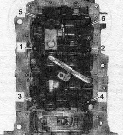
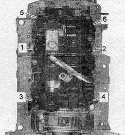
Tighten the balance shaft module bolts in the following order.
| Stage | Bolts | Tightening torque/rotation angle |
| 1 | "1...6" | tighten by hand in the sequence. |
| 2 | "1...6" | pre-tighten the bolts to the torque; 6 Nm |
| 3 | "1...4" | tighten to a torque of 20 Nm |
| 4 | "5 and 6" | tighten to a torque of 13 Nm |
| 5 | -1 — 6- | tighten with a rigid wrench by 90° in sequence. |
Removal and installation of oil. pump
Remove the oil pan. Unscrew the "arrow" bolt and remove the suction pipe from the oil. pump.
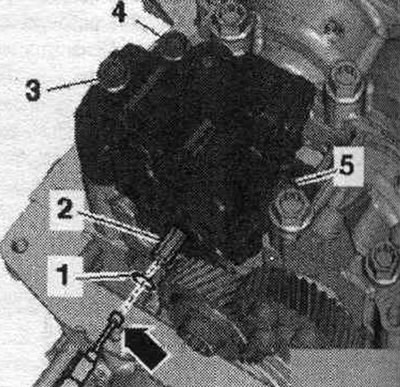
Remove snap ring "1" using snap ring pliers. Remove drive shaft "2" from the oil pump using the "arrow" electromagnet. Unscrew bolts "3, 4, 5" and remove the oil pump. pump. Do not loosen the intermediate gear bolt.
Installation
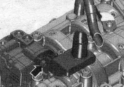
Installation in reverse order. Replace the seal. o-ring. Replace a damaged or stretched snap ring. The retaining ring must fit into the base of the groove. If there are no centering bushings "arrows" in the oil pump, install them. If the balance shaft module does not have installation bushings for centering the oil. pump, insert the mounting bushings. Install the oil pan.
Removal the balance shaft module
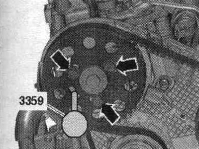
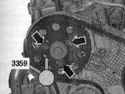
Remove the oil dipstick. Remove the oil pan. Remove the cap from the vibration damper. Using the adapter and a bent socket wrench, turn the crankshaft 1 turn in the direction of engine rotation "arrow" until the crankshaft returns to the "TDC" position.
Risk of damage due to timing belt jumping. Turn the crankshaft only in the direction of engine rotation. Secure the camshaft hub using the fuel pump locking pin. injection "3359". "Arrows" should not be taken into account.
Loosen the bolts in sequence. "6...1". Unscrew the bolts and remove the balance shaft module with the oil pump.
Installing a new balance shaft module
The hub is secured with a 3359 high-pressure fuel pump locking pin. The spur gear of the balance shaft module must be installed with a tooth profile clearance of 0.038–0.072 mm. To achieve the required tooth profile clearance, a coating of the appropriate thickness is applied to the new intermediate gear. The coating is located on separate sections of the perimeter on the teeth. Over a short period of time, the coating wears out and the necessary gap appears. A new balance shaft module should always be installed with a new coated idler gear. Replace bolts that were tightened with additional tightening.
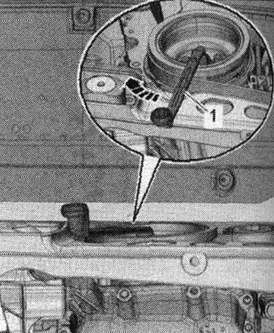
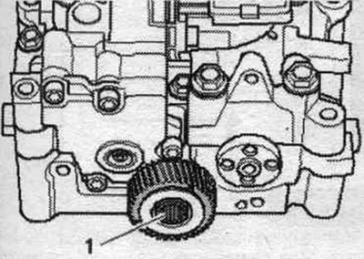
Risk of the thrust bearing washer slipping behind the intermediate gear. When installing the balance shaft module, do not loosen the intermediate shaft gear bolt more than specified. Loosen bolt "1" of the intermediate gear by approximately 45°. If the cylinder block does not have alignment bushings for the balance shaft module, insert the alignment bushings. Install the balance shaft module onto the cylinder block. The intermediate gear coating must not be damaged.
Tighten the balance shaft module bolts.
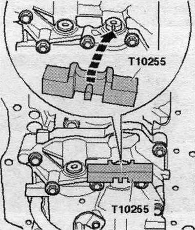
Secure the balance shaft using the locking device "T10255"; if necessary, rotate the shaft. The journal of the locking device must enter the groove of the balance shaft.
Carefully place the gear onto the balance shaft, while moving the intermediate gear slightly to the side. The intermediate gear coating must not be damaged. The threaded holes of the balance shaft should be located, if possible, in the center of the longitudinal holes of the balance shaft gear. If the longitudinal holes in the balance shaft gear do not match the threaded holes, it is necessary to turn the gear by the corresponding number of teeth and re-install it. Tighten the balance shaft gear arrow bolts. Remove the locking device "T10255".
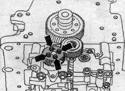
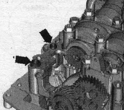
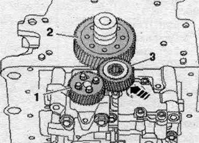
The following 3 stages of work must be completed simultaneously (need help from 2 mechanics). Press intermediate gear "3" firmly, using a wooden block if necessary, in the direction of the arrow, into the gear mesh of gear "2" and balance shaft gear "1". Turn the balance shaft gear slightly counterclockwise. Tighten the idler gear bolts. Remove the locking pin from the diesel fuel injection pump "3359". After installation, there should be no play in the intermediate gear. This can be checked manually without much effort.
Installation in reverse order. Install the oil pan.
Installation of a previously used balance shaft block
The hub is secured with a 3359 high-pressure fuel pump locking pin. When installing the old balance shaft module, provided that neither the crankshaft timing gear nor the crankshaft itself has been replaced, proceed as described below. Under no circumstances should the intermediate gear be unscrewed. If the idler gear bolt has been loosened or removed, or if the crankshaft timing gear or crankshaft itself has been replaced, a new coated idler gear must be installed. Replace bolts that were tightened with additional tightening. Secure the balance shaft using the locking device "T10255"; if necessary, rotate the shaft. The journal of the locking device must enter the groove of the balance shaft. If there are no alignment bushings on the cylinder block for centering the balance shaft module, insert the alignment bushings. Install the balance shaft module onto the cylinder block. With the balance shaft locked, the intermediate gear must mesh with the gear wheel on the crankshaft. The intermediate gear should have a noticeable play in rotation. Tighten the balance shaft module bolts. Remove the locking pin of the diesel fuel injection pump "3359". Installation is in reverse order. Install the oil pan.
(Read the original source on the website: «AUDImanual.ru»)