
Table of contents: Engines 3.0 l 1st generation… ↓ 3.0L SCR engines (SATA, SSMA) until… ↓ 3.0L SCR engines (SATA, SSMA) since… ↓ 4.2L engines ↓
Engines 3.0 l 1st generation (BUG/BUN and CASA/CASB)
1. The intercooler installation details are shown in the illustration.
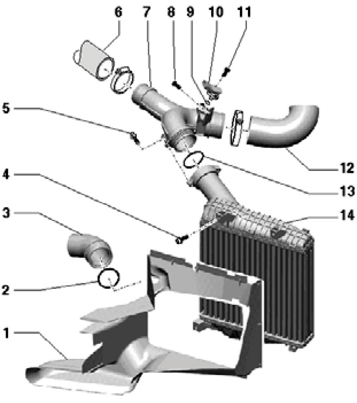
6.1. Installation details of the left intercooler of 3.0 l engines of the 1st generation and SATA/CCMA engines from 06.2010. (right - similarly):
1 - Front air duct;
2 - Sealing ring;
3 - Air hose to turbocharger;
4, 5, 8 - Bolt, 9 Nm;
6 - Air hose to the right intercooler;
7 - Connection;
9, 13 - Sealing ring, subject to replacement;
10 - Boost pressure sensor "G31";
11 - Bolt, 5 Nm;
12 - Air hose to intake manifold;
14 - Intercooler.
2. Remove the front sound insulation panel under the engine compartment and the shroud above the radiator (see Section 19 of Chapter 1).
3. Remove the front bumper cover (see Chapter 10).
4. Remove the bolts on the top of the intercooler (see illustration).
6.4. Upper intercooler mount.
5. Remove the air duct from the intercooler (1 in the illustration).
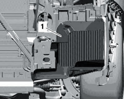
6.5. Air duct on intercooler.
6. Unscrew the bolts and remove the nut (1-3 in the illustration).
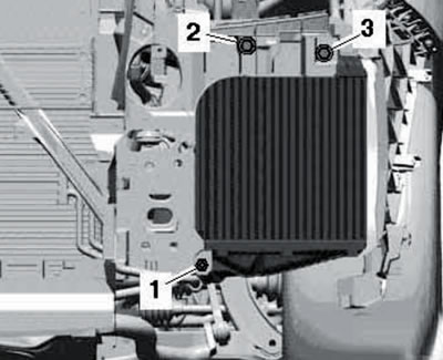
6.6. Front intercooler mount.
7. Pull the locking lever slightly (1 in illustration 3.3 Chapter 3) and remove the intercooler. Disconnect the air tube.
8. Installation is carried out in reverse order.
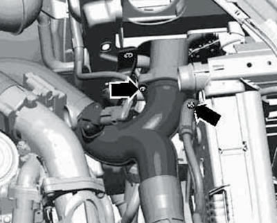
3.0L SCR engines (SATA, SSMA) until 05.2010
9. Details of the installation of the intercooler and the lines of the boost system are shown in the illustrations.
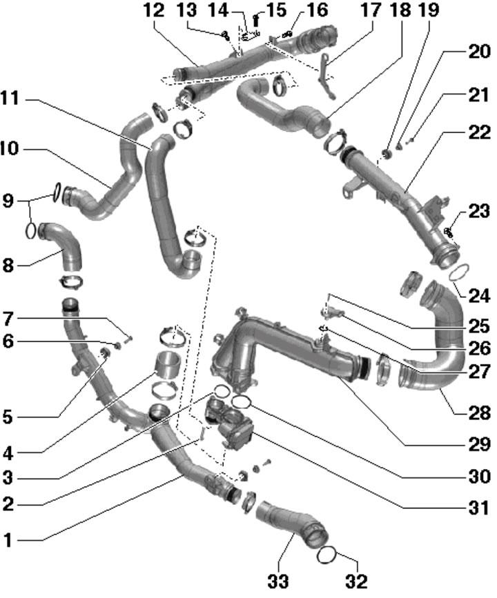
6.9a. Supercharging system lines of SATA and CCMA engines before 05.2010:
1 - Lower air tube;
2, 7, 13, 15, 16, 21, 23, 25 - Bolt, 9 Nm;
3, 30 - Gasket, subject to replacement;
4 - Air hose;
5, 19 - Spacer;
6, 20 - Bushing;
8 - Air hose from the right intercooler;
9, 24, 27, 32 - Sealing rings, subject to replacement;
10 - Air hose to the right intercooler;
11 - Air hose to block 31;
12 - Right air tube;
14 - Right air tube bracket;
17 - Engine lifting eye;
18 - Air hose;
22 - Upper air pipe to left intercooler;
26 - Boost pressure sensor "G31";
28 - Air hose to throttle valve module "J338";
29 - Central air hose;
31 - Control unit "J865" intercooler bypass;
33 - Air hose from the left intercooler.
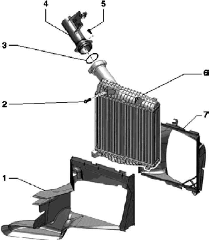
6.9b. Installation details of the left intercooler SATA and CCMA before 05.2010. (right - similarly):
1 - Front air duct, connected to intercooler 2.5 Bolt, 9 Nm;
3 - Sealing ring;
4 - Air tube;
6 - Intercooler;
7 - Rear air duct.
10. Remove the front sound insulation panel under the engine compartment and the shroud above the radiator (see Section 19 of Chapter 1).
11. Remove the front bumper cover (see Chapter 10).
12. Unscrew the bolts (2-5 in Illustration 3.26 of Chapter 3).
13. Remove the bolts (1, 2 and 4 in Illustration 3.27 of Chapter 3) and disconnect the upper air pipe from the intercooler.
14. Remove the air duct from the intercooler (1 in illustration 6.5).
15. Unscrew the bolts and remove the nut (1-3 in illustration 6.6).
16. Lift the latch (1 in illustration 16.7 Chapter 2) and remove the intercooler.
17. Installation is carried out in reverse order.
3.0L SCR engines (SATA, SSMA) since 06.2010 and 3.0 l 2nd generation engines
18. The details of the installation of the boost system lines are shown in the illustrations.
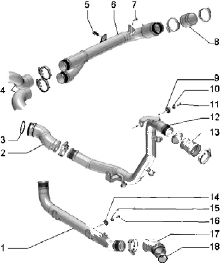
6.18a. Supercharging system lines for SATA and CCMA engines since 06.2010:
1 - Lower air hose;
2 - Air hose;
3, 18 - Sealing ring, subject to replacement;
4, 8, 13 - Air hoses;
5, 7 - Bolt, 9 Nm;
6 - Right air tube;
9, 14 - Spacer;
10, 15 - Bushing;
11, 16 - Bolt, 5.5 Nm;
12 - Central air tube;
17 - Air hose from the right intercooler.
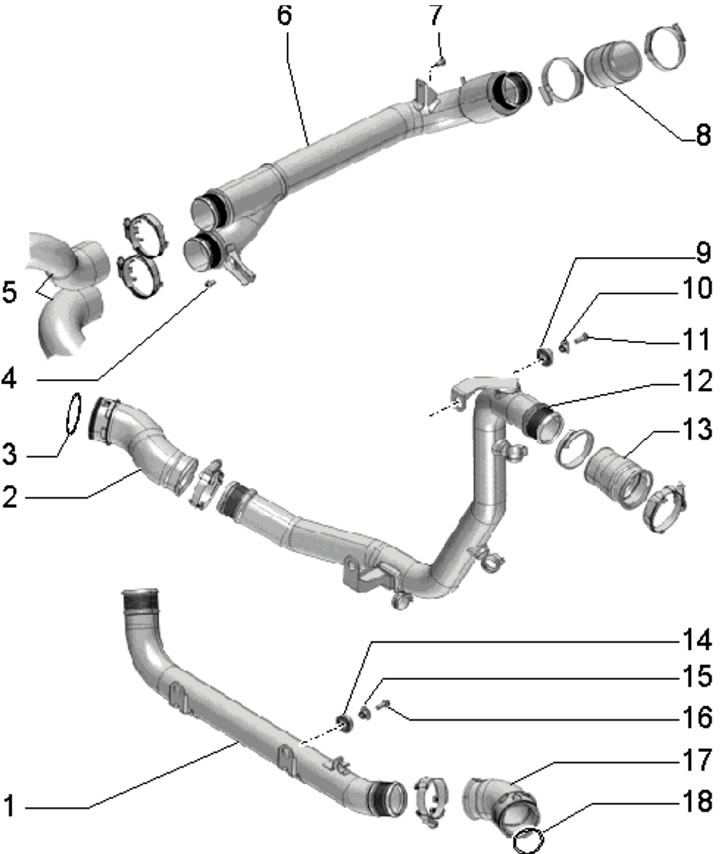
6.18b. Turbocharging system lines for 2nd generation 3.0L engines:
1 - Lower air hose;
2, 5, 8, 13, 17 - Air hoses;
3, 18 - Sealing ring, subject to replacement;
4, 7, 16 - Bolt, 9 Nm;
6 - Right air tube;
9, 14 - Spacer;
10, 15 - Bushing;
11 - Bolt, 5.5 Nm;
12 - Central air tube.
The intercooler installation details are shown in Figure 6.1.
19. Follow the steps described in paragraphs 2-6.
20. Lift the retainer (1 in illustration 3.3 Chapter 3) and remove the intercooler. Installation is carried out in reverse order.
4.2L engines
21. The details of the installation of the intercooler and the lines of the boost system are shown in the illustrations.
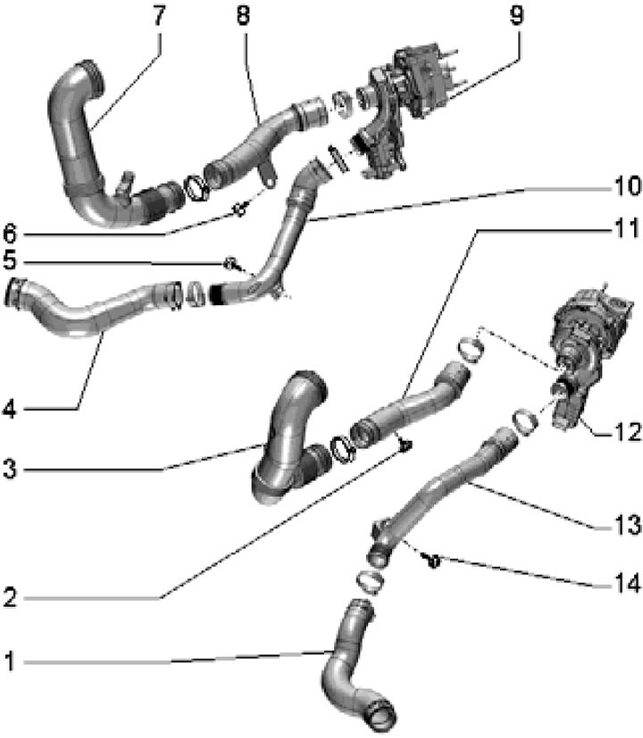
6.21a. 4.2L engine boost system lines:
1 - Air hose to the left intercooler;
2, 5, 6, 14 - Bolt with spacer, 9 Nm;
3 - Air hose from the air cleaner;
4 - Air hose to the right intercooler;
7 - Air hose from air cleaner, with heating element "N79" for PCV;
8, 10, 11, 13 - Air tube;
9 - Right turbocharger.
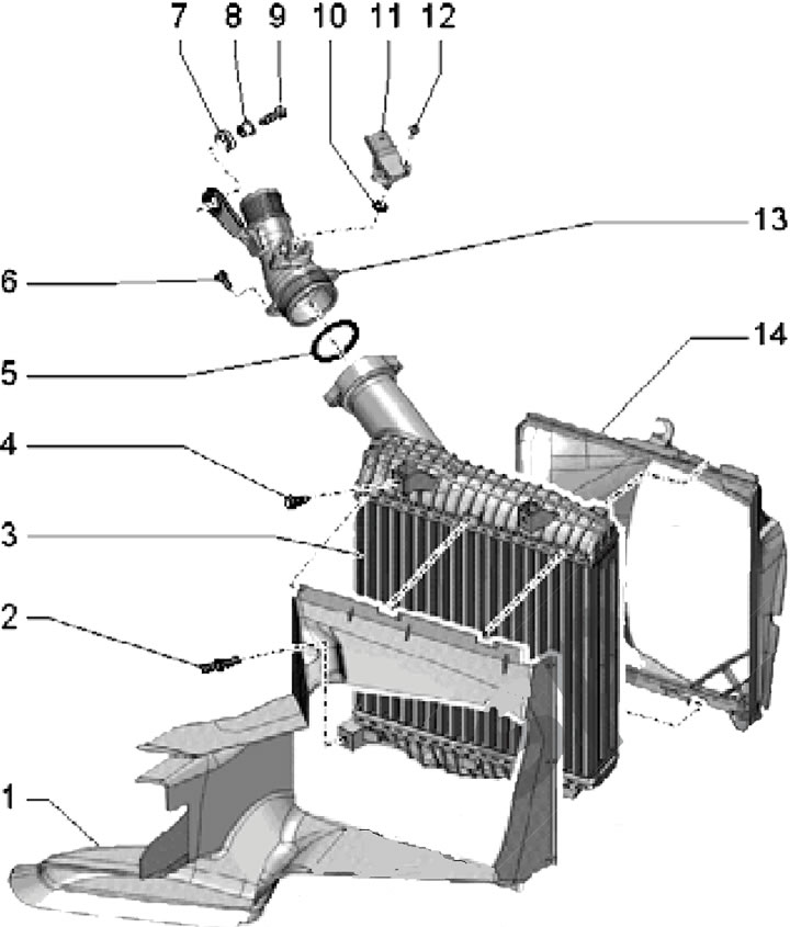
6.21b. Installation details of the left intercooler for 4.2L engines:
1 - Front air duct: connected to the intercooler;
2 - Hexagonal stud, 9 Nm;
3 - Intercooler;
4, 6 - Bolt, 9 Nm;
5, 10 - Sealing ring;
7 - Spacer;
8 - Bushing;
9 - Bolt, 1.7 Nm;
11 - Boost pressure sensor "G31";
12 - Bolt, 5 Nm;
13 - Connection;
14 - Rear air duct.
22. Remove the front sound insulation panel under the engine compartment and the shroud above the radiator (see Section 19 of Chapter 1).
23. Remove the front bumper cover (see Chapter 10).
24. Loosen the clamps (1 and 2 in Illustration 35.19 Chapter 2) and remove the air hose.
25. Disconnect the connector (arrow in illustration 3.48 Chapter 3) boost pressure sensor, unscrew the bolts (1 and 3) and remove the connection from the left intercooler.
26. Remove the air duct from the intercooler (1 in illustration 6.5).
27. Give the nut (2 in the illustration) and move the coolant pipe (1) to the side.
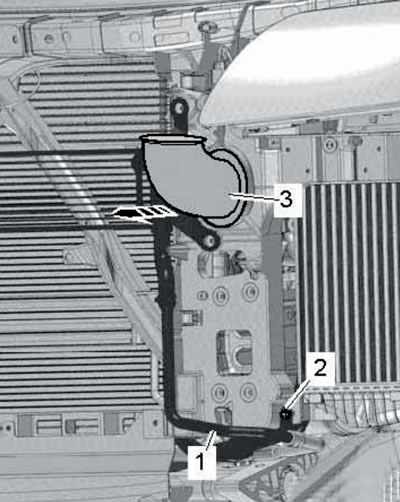
6.27. Removing the tubes.
Pry up the air tube (3) and separate it from the air cleaner in the forward direction (arrow).
28. Disconnect the air hose from the intercooler (1 in illustration 23.2a of Chapter 2), pulling out the latch.
29. Unscrew the pin (1 in illustration 6.6) and bolts (2 and 3), then remove the left intercooler.
30. Installation is carried out in reverse order.
[Read the original source on the website: AUDIMANUAL]