
Caution: After disconnecting the fuel lines, plug the exposed openings to prevent dirt from entering the fuel supply system.
1. The fuel tank installation details are shown in the illustrations.
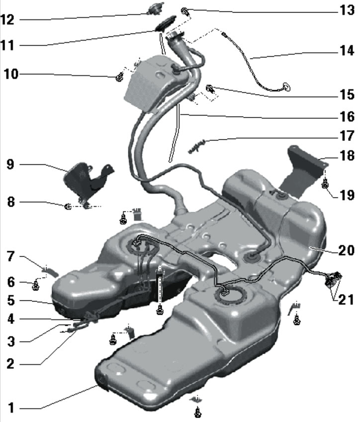
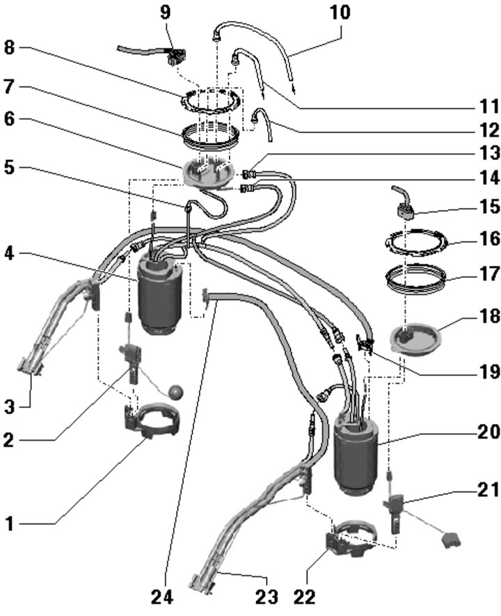
10.1a. Fuel tank installation details for 3.0L (except SCR) and 4.2L models:
1 - Left heat shield;
2 - Fuel supply line to the filter;
3 - Return fuel line, from fuel cooler;
4 - Fuel supply line to the auxiliary heater metering pump;
5 - Right heat shield;
6 - Bolt, 33 Nm;
7 - Mounting clamp, available in different lengths;
8 - Nut, 9 Nm;
9 - Fuel filler neck protective plate;
10, 15 - Bolt, 9 Nm;
11 - Rubber bowl;
12 - Filler cap;
13 - Bolt, 5 Nm;
14 - Mass connection;
16 - Overflow hose;
17 - Ventilation line bracket;
18 - Support bracket;
19 - Bolt, 33 Nm;
20 - Fuel tank;
21 - Electrical connectors for the electric fuel pump and fuel level sensor, pre-10/2006 models only.
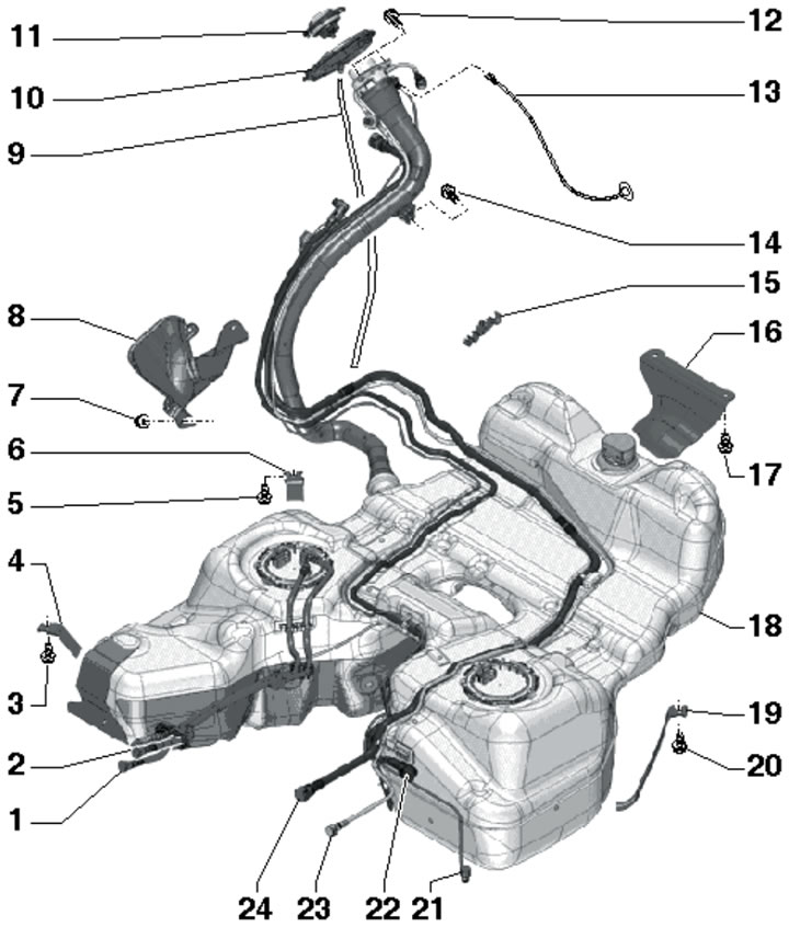
10.1b. Fuel tank installation details for 3.0L SCR models:
1 - Return fuel line, from fuel cooler;
2 - Fuel supply line to the filter;
3, 5, 17, 20 - Bolt, 33 Nm;
4 - Front right clamp;
6 - Rear right clamp;
7 - Nut, 9 Nm;
8 - Protective plate of the filler neck;
9 - Overflow hose;
10 - Rubber bowl;
11 - Filler cap;
12 - Bolt, 5 Nm;
13 - Mass connection;
14 - Bolt, 9 Nm;
15 - Tube bracket;
16 - Support bracket;
18 - Fuel tank with heat shield;
19 - Left clamp;
21 - Transfer line, from the main pump "V436" of "Ad-Blue" liquid to the active tank of this liquid;
22 - Dosing line, from the pump "V437" of the liquid "AdBlue" to its nozzle "N474";
23 - Ventilation line from the passive tank of AdBlue liquid to its active tank;
24 - Filling line, from the passive tank of AdBlue liquid to its active tank.
The following description is given using the 3.0 L (except SCR) and 4.2 L models as an example. On SCR models, the actions are similar.
2. Empty the fuel tank.
3. On models with air suspension, activate the jacking mode (see Introduction).
4. Open the fuel filler flap, turn off the ignition and remove the key from the lock.
5. On models from 11.2006, remove the second row seats, cut the floor covering on the left and right along the perforations, fold it back and loosen the nuts (1 in the illustration) flange covers of both fuel supply modules.
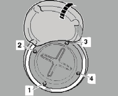
10.5. Flange cover fastening.
Remove the lids. On the left side, disconnect the connector on the fuel delivery module flange.
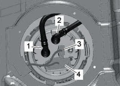
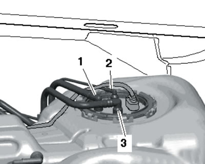
6. On models with a vertical fuel filter, disconnect the return line (1 in the illustration) and the supply (2) fuel lines from the flange of the right fuel supply module.
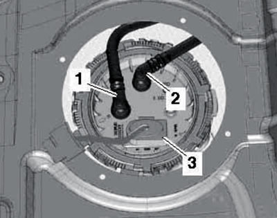
10.6 Connections on the right fuel delivery module (with a vertical filter).
Disconnect the connector (3).
7. On models with a horizontal fuel filter, disconnect the return line (1 in the illustration) and the supply (2) fuel lines from the flange of the right fuel supply module.
10.7. Connections on the right fuel delivery module (with a horizontal filter).
Disconnect the connectors (3 and 4).
8. On models with auxiliary heater, disconnect the fuel supply line going to the auxiliary heater metering pump.
9. Clean the area around the fuel filler neck, remove the cap and seal the neck with a clean plug to prevent dirt from getting into the tank.
10. Remove the fuel filler cap assembly (see Chapter 10).
11. Pry up the rubber cup (1 in the illustration) and take it off.
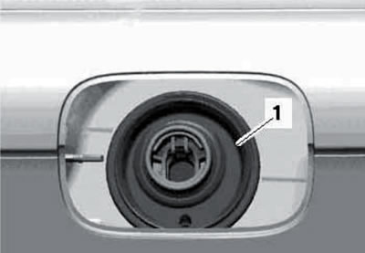
10.11. Removing the rubber cup.
12. Unscrew the neck mounting bolts (see illustration).
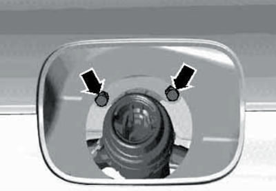
10.12. Filler neck bolts.
13. Remove the rear suspension subframe and tie up the driveshaft (1 in the illustration) on the body using a chain or a bent welding electrode, as shown in the illustration.
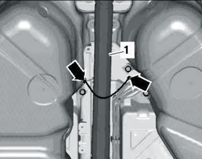
10.13. Tying up the cardan shaft.
14. Lower the rear end of the driveshaft to a distance (and in the illustration) = 220 mm.
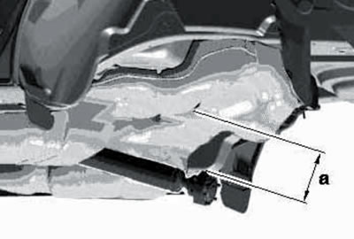
10.14. Lowering the cardan shaft.
Note: Do not bend the shaft joints more than 10°.
15. Remove the right rear wheel arch liner (see Chapter 10), disconnect the ground wire from the filler neck (1 in the illustration) and unscrew its bolts (2 and 3).
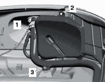
10.15. Wire (1) and bolts (2 and 3) of the filler neck.
16. Unscrew the nuts (arrows in the illustration) and remove the protective neck plate.
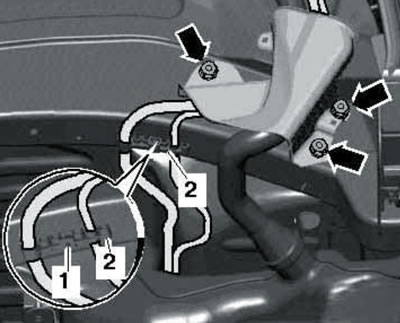
10.16. Protective plate and bracket.
Knock out the pin (1) and remove the bracket (2) from the side member together with the ventilation lines.
17. On models before 10.2006, disconnect the connectors (1 and 2 in the illustration) fuel pumps and fuel level sensors (on the left side member).
10.17. Connectors near the fuel tank.
18. Remove the bolts of the central bottom panel on the left and right in the area of the fuel tank. Release the feeder (1 in the illustration) and return (3) fuel lines from the fuel tank and from the bracket (arrows).
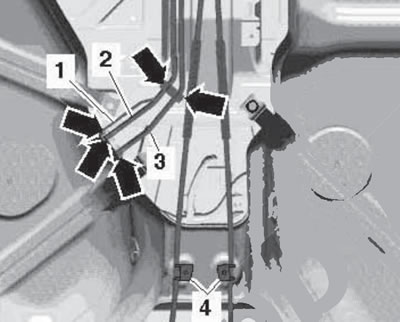
10.18. Fastening fuel lines and parking brake cables.
Unhook the parking brake cable holders (4) from the tank. On models with an additional heater, also disconnect the fuel supply line (1) to the fuel metering pump.
19. Support the fuel tank as shown in the illustration.
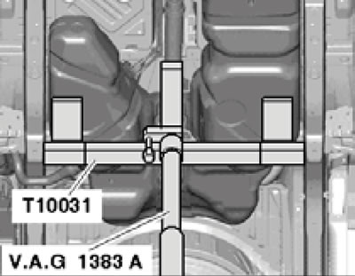
10.19. Fuel tank supports.
Additionally, ask an assistant to hold the tank with his hand.
20. Mark the installation position of the tank clamps and unscrew the bolts (1-12 in the illustration) and remove the clamps and support bracket.
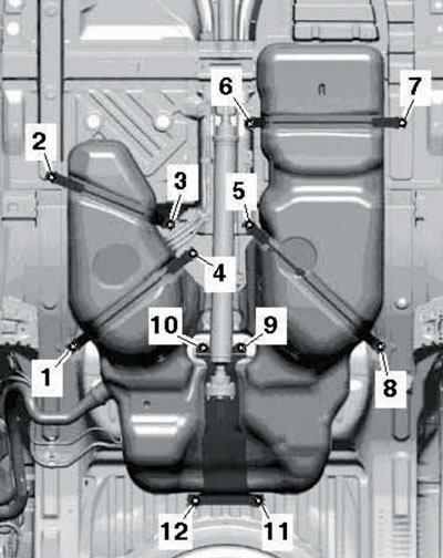
10.20. Fuel tank clamps.
Have an assistant hold the tank from behind and lower the tank until it touches the driveshaft. Carefully remove the filler neck from the wheel arch, avoiding damage to the paintwork.
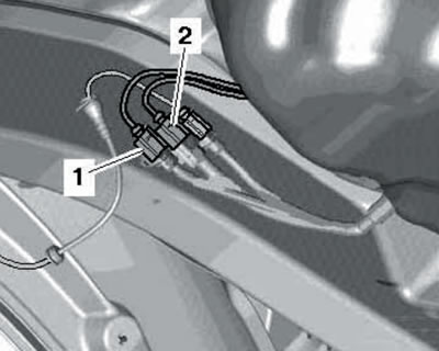
21. On models up to 10.2006, disconnect the supply line through the opening between the body and the tank (1 in the illustration) and return (3) fuel lines.
10.21 Fuel line connections on models before 10.2006.
On models with an additional heater, also disconnect the fuel supply line (1) to the fuel metering pump.
22. Lower the tank.
23. If necessary, remove the fuel tank components, referring to Illustrations 10.23a-b.
10.23a. Installation details of the fuel delivery module, jet pump and fuel level sensors for models up to 05.2008, except 3.0 L SCR:
1, 22 - Retaining ring, welded to the tank;
2 - Fuel level sensor "G", fixed in ring 1;
3 - Right jet pump, for module 20, fixed in ring 1;
4 - Right fuel supply module, with booster pump "G6": inserted into ring 1 and turned 15° clockwise;
5 - Fuel supply line to the additional heater;
6 - Right flange;
7, 17 - Gasket, subject to replacement, installed dry;
8 - Retaining ring, 110 Nm;
9 - Connector of booster pump "G6" and fuel level sensor "G";
10 - Fuel return line from the fuel cooler, fixed to the tank;
11 - Fuel supply line to the filter, fixed to the tank;
12 - Fuel supply line to the auxiliary heater metering pump, fixed to the tank;
13 - Fuel return line;
14 - Fuel supply line;
15 - Connector for electrical wiring of pump "G23" and fuel supply sensor No. 2 "G169";
16 - Retaining ring;
18 - Left flange;
19 - Fuel supply line, fixed to module 20;
20 - Left fuel supply module, with fuel pump "G23", inserted into ring 22 and turned 15° clockwise;
21 - Sensor No. 2 "G169" fuel supply, fixed on ring 22;
23 - Left jet pump, for module 4, fixed to ring 22;
24 - Fuel supply line, fixed to module 4.
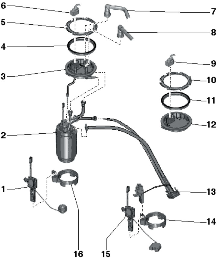
10.23b. Installation details of the fuel delivery module, jet pump and fuel level sensors for models from 06.2008 and 3.0L SCR models:
1 - Fuel level sensor "G", fixed in ring 16;
2 - Fuel supply module, with booster pump "G6"; inserted into ring 16 and turned 15° clockwise;
3 - Right flange;
4, 11 - Gasket, subject to replacement, installed dry;
5, 10 - Retaining ring, 110 Nm;
6 - Connector of the booster pump "G6" and the fuel level sensor "G";
7 - Fuel return line from the fuel cooler, fixed to the tank;
8 - Fuel supply line to the filter, fixed to the tank;
9 - Sensor wiring connector 15;
12 - Left flange;
13 - Jet pump, fixed in ring 14;
14, 16 - Retaining ring, welded to the tank;
15 - Fuel level sensor No. 2 "G169", fixed on ring 14.
Paw (2 in illustration 10.23c) the flange should be in front and located between the projections (1 and 3) on the tank.
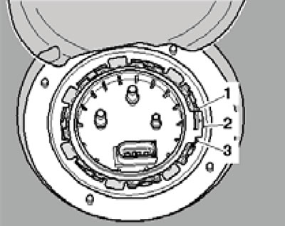
10.23s. Installation position of the flange of the right fuel supply module (left - similarly).
24. Installation is carried out in reverse order. When securing the tank, first tighten the support bracket fasteners (1 in illustration 10.20), then - fastening the rear clamps (1, 4, 5 and 8), and then - fastening the front clamps (2, 3, 6 and 7).