
Table of contents: Removal ↓ Installation ↓
Fuel pump with fuel level sensor. Petrol engine of all-wheel drive model
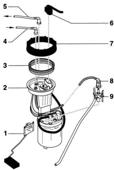
- 1 — Fuel gauge sensor
- 2 — Fuel supply unit
- 3 — Sealing ring
- 4 - Fuel return line. Do not kink it
- 5 - Fuel supply line. Do not kink it
- 6 — Connector
- 7 — Union nut, 80Nm
- 8 — Jet hose
- 9 — Ejector. For vehicles with parking heater since 2/03 release with parallel installation of the suction line of the parking heater
The fuel pump is located together with the fuel level sensor in the fuel tank. All-wheel drive models, due to the need to accommodate the propeller shaft, have a fuel tank consisting of two parts. In this case, each chamber has its own fuel level sensor. The right chamber contains an electric fuel pump.
The illustration above shows the fuel pump of a petrol engine of all-wheel drive vehicles. The description also applies to vehicles with a 1.9L diesel engine, as well as to 2.5L diesel engines from 5/02 release.
The fuel gauge consists of a float and a potentiometer. When the fuel level drops, the float of the gauge also drops. The potentiometer, connected to the float, increases the electrical resistance of the gauge. This reduces the voltage on the instrument panel and moves the fuel gauge toward "empty". In vehicles with a two-part fuel tank, the instrument panel processor calculates the total fuel level based on the signals from the two gauges and then outputs a signal to the fuel gauge.
Warning: On vehicles with direct injection petrol engines, a fuel pressure regulator is built into the fuel supply unit. The pressure regulator cannot be disconnected from the fuel supply unit.
When removing the fuel pump, some fuel may leak out. Fuel vapors are toxic and flammable. Therefore, ensure that the work area is well ventilated. Use gloves that are resistant to fuel. Do not use open flames, fire hazard! Keep a fire extinguisher at hand.
Before removing the fuel pump and sensor, empty the fuel tank as much as possible. The tank should be no more than 2/3 full. A radial fan with an electric motor located outside the air flow and a capacity of at least 15 m³/hour can be used to ventilate the work area.
Front wheel drive models
Removal
1. Disconnect the negative (-) battery cable.
Warning: Follow the instructions in Section Replacing the battery.
2. Sedan: Fold the right rear seatback forward if necessary. Remove the trunk trim, refer to Section Removal and installation trim (Sedan).
3. Station wagon: Remove the left backrest, as well as the left trunk trim and mud tray, refer to Section Removal and installation trims (Universal).
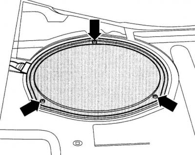
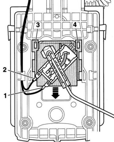
4. Remove the cover for the shut-off flange (arrows in the accompanying illustration).
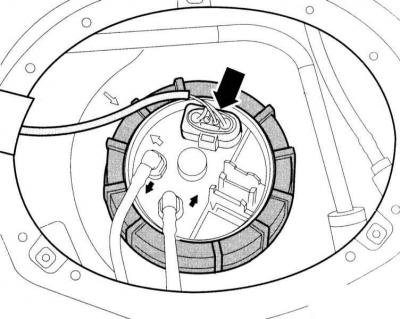
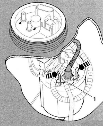
5. Carefully loosen the 4-pin fuel level sensor and fuel pump connector with your hand or a small screwdriver (arrow on the accompanying illustration) and disconnect it.
Warning: The fuel supply line is under pressure! Before opening the hose connection, cover it with a thick cloth. Then relieve the pressure by carefully disconnecting the hose. Wear protective glasses.
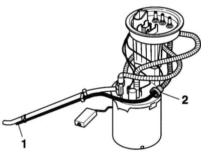
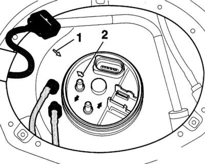
6. Mark the fuel lines (1/2) with a felt-tip pen before disconnecting.
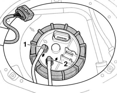
7. Disconnect the supply and return pipes (1) (2) by squeezing the locking keys on the couplings. Close the pipes with suitable plugs or adhesive tape.
8. Models with parking heating: Additionally, disconnect the fuel supply line to the parking heater.
9. Unscrew the union nut using special tool 3217.
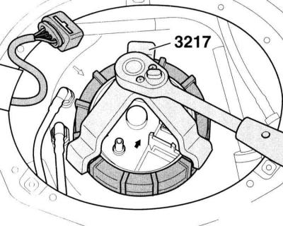
Warning: If the specified tool is not available, loosen the union nut by lightly striking it with a hammer through a wooden block.
Caution: Avoid sparking.
10. Remove the fuel injection unit/stock sensor and sealing ring from the fuel tank opening slightly.
11. Move the shut-off flange slightly to the side with the fuel supply unit inserted into the fuel tank.
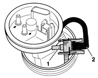
12. Release the ejector (1). To do this, grasp it with your hand through the gap between the locking flange and the installation hole in the fuel tank.
13. Remove the ejector (1) with the drive jet hose (2) still attached upwards.
14. Disconnect the power flow hose from the ejector by pressing the locking button.
15. Models with parking heating from 2/03 release: Disconnect the suction hose (1) for the auxiliary heating at the connection (2). To do this, press the locking button.
16. Remove the ejector.
17. Remove the fuel supply unit.
18. Drain the fuel from the fuel supply unit into the tank or some other container.
19. If necessary, remove the fuel level sensor. To do this, disconnect the connectors (1) and (2). Use a screwdriver to lift the support strips (3) and (4) and remove the sensor downwards (arrow on the accompanying illustration).
Installation
1. If necessary, insert the reserve sensor into the guides on the fuel supply unit and press upwards until the sensor is fixed. Fix the connector. Check the reliability of the fastening.
2. Place the discharge hose onto the ejector connection.
3. Insert the fuel supply unit into the tank.
4. Secure the ejector to the fuel supply unit. To do this, grasp it with your hand through the gap between the locking flange and the installation hole of the fuel tank.
Caution: The ejector must clearly lock into place.
5. Insert the new sealing flange into the fuel tank opening.
6. Check the position of the fuel supply unit: The mark on the shut-off flange (2) must match the mark on the fuel tank (1). If necessary, carefully turn the supply unit.
7. Tighten the union nut of the locking flange with special tool 3217 to a torque of 80 Nm. You can tighten the nut with light hammer blows through a wooden block. Avoid sparks!
8. Put on the supply and return hoses in accordance with the applied marks. At the same time, fix the quick-release couplings. The arrows on the flange indicate the direction of the liquid flow.
9. Connect the 4-pin connector.
10. Connect the negative (-) battery cable.
Warning: Follow the instructions in Section Replacing the battery.
11. Further installation is carried out in the reverse order of removal.
All-wheel drive and front-wheel drive models with a 6-cylinder diesel engine produced before 4/02
To unscrew the locking ring, key 3087 is required. Tightening torque 145 Nm.
Caution: The shut-off flange may only be opened when the fuel tank is no more than 1/4 full. Otherwise, a large amount of fuel will leak out.
The fuel pump with reserve sensor 1 is installed in the right chamber. Reserve sensor 2 is installed in the left tank.
All-wheel drive vehicle, as well as front-wheel drive vehicle with 6-cylinder diesel engine produced before 4/02: The fuel pump is fixed with a bayanet lock. To remove it, turn it to the left at an angle of 15° with a special tool. When installing, turn it to the right accordingly. On the bayanet lock there are two notches and an arrow pointing in the direction "closed".