Table of contents: Removal ↓ Installation ↓
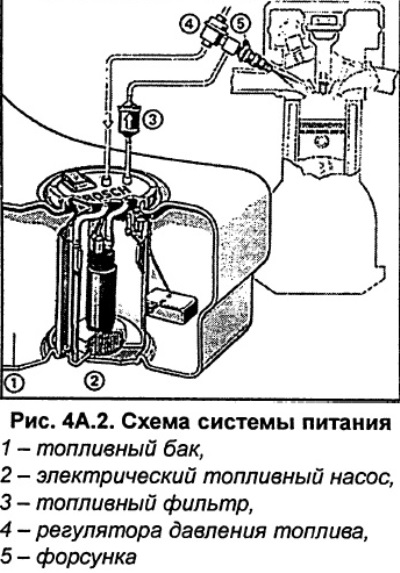
On models with petrol engines, the fuel pump and fuel level sensor are installed in the fuel tank. On front-wheel drive vehicles with a diesel engine,
1.9-I fuel from the fuel tank is taken by a high-pressure fuel pump and only a fuel intake is located in the tank. On all-wheel drive vehicles with 1.9-I 115/130 hp diesel engines, a fuel pump is installed in the fuel tank.
Structurally, it consists of a potentiometer and a float connected to it. When the fuel in the tank decreases, the sensor float drops and, increasing the resistance of the potentiometer, reduces the voltage on the fuel level indicator located in the instrument cluster.
Note: All-wheel drive vehicles have three fuel level sensors. This is because the fuel tank has a complex, stepped design. The fuel level sensor also contains the fuel pump, located on the right under the rear seat.
Safety instructions. When removing the fuel pump, a small amount of fuel may spill. Fuel vapors are toxic and flammable, so ensure that the work area is well ventilated. Avoid contact with skin. Use fuel-resistant gloves. Do not use open flames - fire hazard! Make sure that a charged fire extinguisher is in the immediate vicinity of the work area.
Before removing the fuel tank, use up as much fuel as possible from the tank. A radial fan with an electric motor located outside the air flow can be used to ventilate the work area.
Removal
Turn off the ignition and remove the ground wire from the battery.
Attention
- When disconnecting the wires from the battery terminals, the memory units of the control units erase the data on the recorded faults, so before disconnecting the wires, you must contact a workshop to recall the faults recorded in the memory. After connecting the wires to the battery terminals, it is necessary to activate and reprogram the electric windows, as well as the position of the rear-view mirrors and seats.
- If the car has a radio receiver with a code, then before disconnecting the wires from the terminals from the battery, check that there is a code to reactivate the receiver. Otherwise, the radio receiver can only be put into operation at a specialized station.
Front wheel drive cars.Remove the carpet in the trunk and unscrew and remove the fuel level sensor/fuel pump access cover.
All-wheel drive vehicles. Remove the rear seat to access the fuel pump/sender.
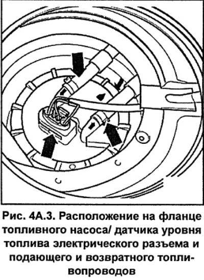
Disconnect the connector from the fuel level sensor/fuel pump (see Fig. 4A.3).
Safety instructions. The fuel line supplying fuel is under pressure. Before disconnecting the fuel line, relieve the pressure in the fuel system. To do this, loosen the clamp securing the fuel line, then cover the connection with a rag and, being careful, remove the fuel hose from the fitting. Use safety glasses to protect your eyes from fuel.
Loosen the clamps and remove the supply and return fuel lines from the fittings of the mounting flange (see Fig. 4A.3). Close the ends of the fuel lines with suitable plugs.
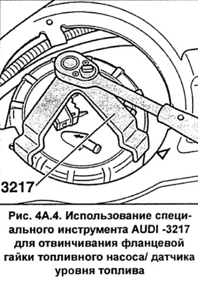
Using the special tool AUDI-3217, unscrew the flange nut (see Fig. 4A.4). To unscrew the flange nut on all-wheel drive vehicles, you must use a special tool AUDI-3087. If you do not have such a tool, unscrew the flange nut using a wooden block and a hammer.
Remove the mounting flange and sealing ring from the fuel tank opening.
From the underside of the mounting flange, label and disconnect the electrical connectors and fuel hoses.
All-wheel drive vehicles.Hold the fuel line to the second fuel level sensor.
From the underside of the flange, support the fuel lines, label and disconnect the electrical connectors.
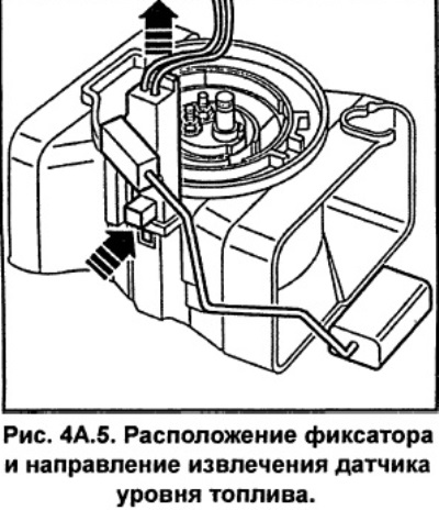
Cars with gasoline engines. Remove the fuel level sensor while simultaneously pressing the lock on the housing (see fig. 4A.5).
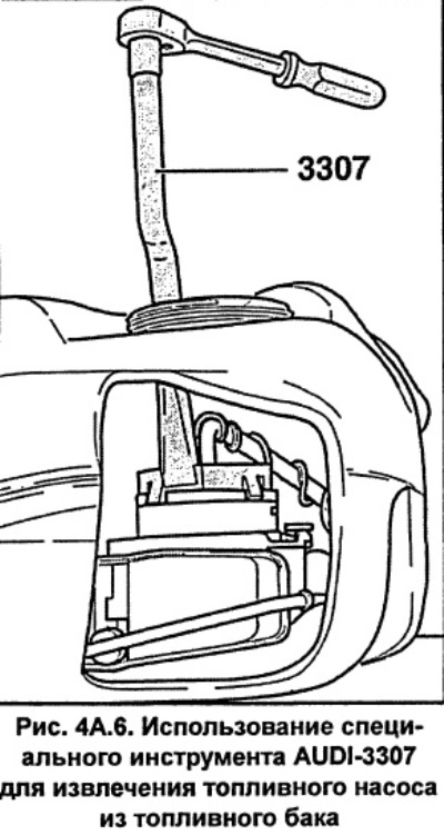
Cars with petrol engines. Using the special tool AUDI-3307, release the fuel pump from the retainer by turning it 15° and remove the fuel pump from the tank (see fig. 4A.6). The special tool is fixed in the slots of the fuel pump body.
Drain the fuel from the fuel pump into a suitable container.
Vehicles with diesel engines: Remove the fuel level sensor from its clips and take it out of the fuel tank.
Installation
Before installation, dip the fuel pump/fuel level sensor O-ring into fuel.
Cars with gasoline engines. Install the fuel pump so that mark 1 (Fig. 4A.7) on the pump aligns with mark 2 on the housing.
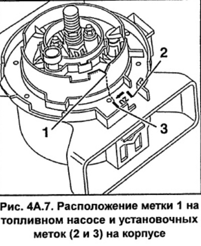
Using the special tool AUDI-3307, turn the fuel pump clockwise until it stops, while mark 1 (Fig. 4A.7) should align with mark 3 on the housing.
Secure the fuel level sensor to the clips.
From the bottom side of the flange, connect the fuel lines and electrical connectors according to the previously applied marks. Secure the fuel lines with new clamps.
Cars with petrol engines: Install the mounting flange so that the mark on the flange aligns with the mark on the fuel tank (see fig. 4A.8).
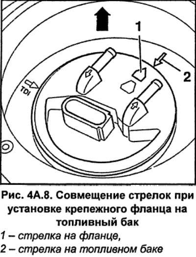
Attention: On vehicles with diesel engines, the arrow on the flange must be aligned with the "TDI" mark on the fuel tank.
Screw on the flange nut and, using the special tool AUDI-3217, tighten it to a torque of 80 Nm. If you do not have such a tool, screw on the flange nut using a wooden block and a hammer.
Place the supply and return fuel hoses on the fitting of the mounting flange and secure them with new clamps. The arrows on the fittings indicate the direction of fuel flow. The return fuel hose is blue.
Connect the electrical connector to the mounting flange.
Place the cover over the mounting flange and screw it in place.
After completing the assembly, check that the fuel and ventilation lines are properly secured to the fuel tank.
Place a floor mat in the trunk. In all-wheel drive vehicles, install a rear seat.
Connect the ground wire to the battery. Repeat the steps to memorize the position of the seats, mirrors, etc., and also set the time on the clock and enter the code into the radio.