
Repair Chevrolet Repair Toyota Repair Honda Repair AvtoVAZ Repair Mercedes-Benz Repair BMW Repair Opel
Home  |  Contacts  |  Sitemap  |    
English Русский
Български
Беларускі
Український
Српски
Hrvatski
Română
Polski
Slovenský
Magyar
AudiManual.ru


  • AUDI 80
  • AUDI 100
  • AUDI A3
  • AUDI A4
  • AUDI A6
  • AUDI A8
  • AUDI Q
  • OTHER
  • ARTICLES
C5 Allroad (1999-2005) C5 (1997-2004) C4 (1994-1997)

General information (Audi A6 C5)

  • Home
  • Audi A6
  • C5 (1997-2004)
  • Power unit
  • Fuel system
  • General information
            0
Table of contents: Economy driving mode ↓ Safety rules when working on the… ↓
The fuel system includes the fuel tank, fuel lines, fuel filter, fuel pump and injection device (separate chapter).

The plastic fuel tank is located under the vehicle's underbody behind the rear axle. The amount of fuel in the tank is displayed by a fuel gauge located in the instrument cluster. The fuel tank is ventilated by a closed ventilation system. Harmful gasoline vapors from the fuel tank ventilation are captured by an activated carbon accumulator.

Economy driving mode


The way you drive your car has a significant impact on fuel consumption.
  • After starting the engine, start driving immediately, even in freezing temperatures.
  • If stops are expected to last more than 40 seconds, turn off the engine.
  • Drive in the highest possible gear.
  • Try to maintain a constant speed on the longest possible sections of the road, avoid high speeds. When driving, be prudent, and do not brake unnecessarily.
  • Do not carry unnecessary additional cargo in your vehicle; remove any attachments, such as roof racks, from your vehicle as soon as possible.
  • Check tire pressure regularly, do not operate the vehicle with low tire pressure.

Safety rules when working on the fuel system


When working on the fuel system, observe the following safety and hygiene rules:

Safety instructions
  • When working on the fuel system, do not use open flames, electric welding or tools that may generate sparks. Make sure that a charged fire extinguisher is in the immediate vicinity of the work area.
  • Work on the fuel system must be carried out in a well-ventilated area, for which you can open all windows and doors to create a draft.
  • The fuel system is under pressure. When disconnecting system components, fuel may splash out, so use goggles to protect your eyes from fuel getting into them. If fuel gets on your skin, rinse the area with plenty of water. Collect any leaking fuel with a rag.


Hoses are secured to pipelines using band clamps or clamping brackets. Clamping brackets are replaced with band clamps during repairs. The use of clamping or screw clamps is not permitted. Special pliers, such as HAZET 798-5, are used to install band clamps.


  • Before disconnecting, thoroughly clean the connection points and adjacent areas.
  • Place the removed parts on a clean surface and cover them with foil or paper. Do not use fibrous rags.
  • Close or plug open connections if repairs are to be made over a period of time.
  • Install only clean parts. Remove spare parts from their packaging immediately before installing them. Do not use parts that are not packaged (for example, in toolboxes, etc.).
  • If possible, do not work with compressed air when the fuel system is open. Try not to move the car.
  • Do not use silicone-containing sealants. The residues of silicone components sucked in by the engine do not burn in the engine and damage the lambda sensor.
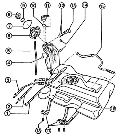
1 - ventilation hose,
2 - return pipeline,
3 - fuel supply line to the filter,
4 - bolt,
5 - overflow hose,
6 - rubber cup,
7 - ring,
8 - cover,
9 - sealing ring,
10 - sealing ring,
11 - valve,
12 - sealing ring,
13 - air valve,
14-connection to "mass"
15 - ventilation hose,
16 - fuel tank,
17 - fuel tank mounting straps,
18 - bolt.
The article was checked by auto expert Alexey Ivanov
This article is available at russian, bulgarian, belarusian, ukrainian, serbian, croatian, romanian, polish, slovak, hungarian

Share information:
Previous articles
Audi A6 C5: Fuel system
Next articles

Fuel pump/fuel level sensor
Fuel filter
Accelerator cable
Checking the fuel pump control circuit


Link to this page in different formats


Visitor comments

No comments yet


How much will 30 + 38 =


A6(C5 AR, 1999-2005) 
  • General information
  • User manual
  • Maintenance
  • Troubleshooting
  • Power unit
  • V6 petrol engines
  • V8 petrol engines
  • Diesel engines
  • Cooling and heating system
  • Injection system (gasoline)
  • Fuel system (diesel)
  • Supply system
  • Exhaust system
  • Ignition system
  • Transmission
  • Clutch
  • Mechanical gearbox
  • Automatic gearbox
  • Chassis
  • Brake system
  • Car suspension
  • Steering
  • Body
  • Body elements
  • Doors, locks and windows
  • Electrical equipment
  • Equipment and devices
  • Power devices
  • Electrical circuits
  • Schemes (petrol engine 2.7 l)
  • Schemes (petrol engine 4.2 l)
  • Schemes (diesel engine 2.5 l)
 
A6(C5, 1997-2004) 
  • General information
  • User manual
  • Maintenance
  • Power unit
  • Engine repair
  • Cooling system
  • Fuel system
  • Engine management
  • Fuel system (diesel)
  • Exhaust system
  • Transmission
  • Clutch
  • Car gearbox
  • Chassis
  • Front suspension
  • Rear suspension
  • Steering
  • Wheels and tires
  • Brake system
  • Body
  • Exterior
  • Interior
  • Electrical equipment
  • Air conditioner
  • Equipment and devices
  • Electrical circuits
 
A6(C4, 1994-1997) 
  • General information
  • User manual
  • Maintenance (gasoline)
  • Maintenance (Diesel)
  • Gasoline engines
  • 4 cylinder engines
  • 5 cylinder engines
  • 6 cylinder engines
  • Diesel engines
  • 4 cylinder engines
  • 5 cylinder engines
  • Engine repair
  • Removal and reassembly
  • Cooling system
  • Single point injection system
  • Multipoint injection system
  • MPI/MPFI injection system
  • Fuel system (diesel)
  • Exhaust system
  • Ignition system
  • Transmission
  • Clutch
  • Manual transmission
  • Automatic transmission
  • Drive shafts
  • Chassis
  • Brake system
  • Front suspension
  • Rear suspension
  • Steering
  • Body
  • Exterior (external elements)
  • Interior (internal elements)
  • Electrical equipment
  • Power devices
  • Lighting and appliances
  • Electrical circuits
 
AudiManual.ru © 2017-2026 · Mobile version · Feedback · Sitemap: EN BG BY UA RS HR RO PL SK HU · Site search · News and articles
80 B2 · 80 B3 petrol · 80 B3 · 80 B4 · 100 C3 diesel · 100 C3 petrol · 100 C3 · 100 C4 petrol · 100 C4 · A3 Type 8L · A4 B5 petrol · A4 B5 · A4 B6 petrol · A4 B6 · A4 B7 · A4 B8 · A6 C4 · A6 C5 · A6 C5 Allroad · A8 D2 · Q5 Type 8R · Q7 Typ 4L · Audi A2 ·
This site uses cookies 🍪. Click the button to accept this fact.