
Table of contents: Petrol engine 2.5-I-V6-TDI ↓ Checking the voltage supply ↓ Checking the performance of the fuel… ↓
Petrol engine 2.5-I-V6-TDI
The fuel pump is located in the fuel tank.
Safety instructions: When working on the fuel system, do not use open flames or tools that may create sparks. Make sure that a charged fire extinguisher is in the immediate vicinity of the work area.
Fuel vapors are toxic, so work on the fuel system must be carried out in a well-ventilated area.
The fuel system is under pressure. When disconnecting system components, fuel may spray out, so wear goggles to protect your eyes from fuel getting into them.
Check the battery voltage, which should be at least 11.5 V.
Checking the voltage supply
Check the condition of fuel pump fuse #28. If the fuse is blown, replace it.
Turn on the starter briefly, you should hear a short click (about 1 sec) fuel pump operation. The noise of the fuel pump operation can be heard near the fuel tank.
If the fuel pump does not operate, check the fuel pump control circuits (see above).
Turn on switch 1 (fig. 4A.14). If the pump starts working, check the fuel pump relay.
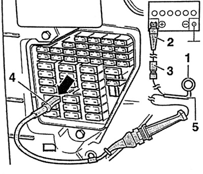
Fig. 4A.14. Tools required to check the fuel pump power supply circuit
1 - switch,
2 - "Alligator" clip (with a wire that provides connection to the battery),
3 - movable fuse for 8 As with wires,
4 - single-pin electrical connector (connects instead of the fuel pump fuse),
5 - two-core wire with a cross-section of 1.5 mm² and a length of 5 m.
If the fuel pump does not work, do the following.
Unscrew and remove the fuel level sender/fuel pump access cover. Disconnect the fuel level sender/fuel pump connector (see fig. 1).
Connect an LED tester or voltmeter to the external contacts of the connector disconnected from the fuel pump (see fig. 4A.15).
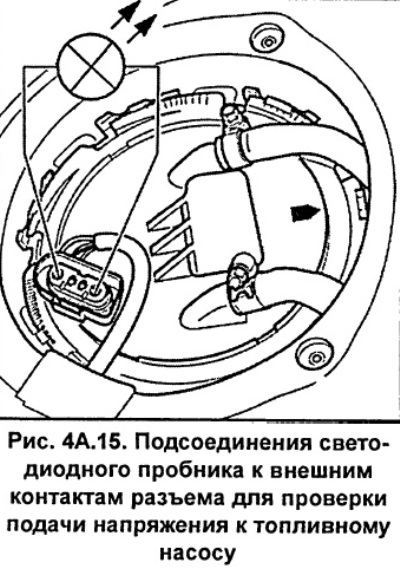
Turn on switch 1 (fig. 4A.14). The voltmeter should show the battery voltage (12 V). Otherwise, check the condition of the wires supplying voltage to the fuel pump.
If the voltmeter shows battery voltage, remove and check the fuel pump.
Check the reliability of the electrical connector connection between the flange and the fuel pump. Also check the condition and resistance of the wires going to the fuel pump. If necessary, use auxiliary lines.
If the test does not produce any results, then the fuel pump is faulty and must be replaced.
Install the fuel pump and connect the electrical connectors to it.
Checking the performance of the fuel pump
Remove the cap from the fuel tank filler neck.
Remove the engine cover and unscrew the spark plugs.
Safety note: The fuel system is under pressure. Before disconnecting the fuel lines, relieve the pressure in the fuel system. To do this, cover the connection with a rag and, being careful, disconnect. When disconnecting the system components, fuel may splash, so use glasses to protect your eyes from fuel getting into them.
Disconnect the fuel return line from the fuel line (see fig. 4A.16).
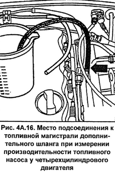
Instead of the return fuel line, connect an additional hose to the fuel line, the free end of which is lowered into a measuring vessel (see fig. 4A.16).
Connect a voltmeter to the battery terminals.
Turn on switch 1 for 15 seconds, while using a voltmeter, determine the battery voltage (fig. 4A.14).
Using the graph shown in Figure 4A.17, determine the fuel pump performance, keeping in mind that when the starter is running, the voltage decreases by 2 V.
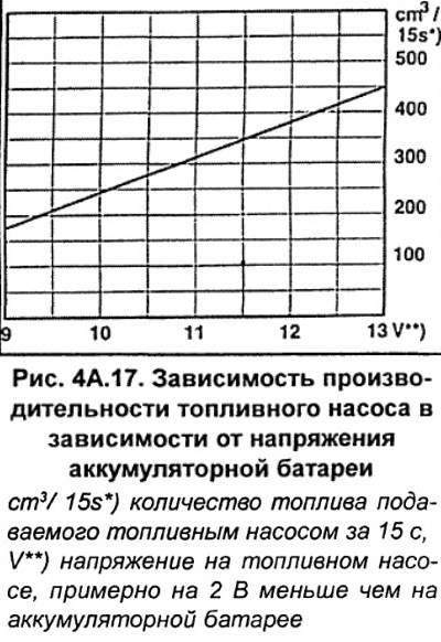
Compare the volume of fuel in the graduated vessel with the data obtained from the graph.
Example: When checking the performance, the battery voltage was 12.5 V. Since the voltage at the fuel pump is about 2 V less than that at the battery, the voltage at the fuel pump is 10.5 V (12.5 - 2 = 10.5). This voltage corresponds to a fuel pump performance of about 275 cm³/15s.
If the voltage supplied to the fuel pump is normal, but the fuel pump performance is low, make sure that the fuel lines are not pinched or dirty inside.
Also check if the fuel filter is dirty. Check the fuel pump performance with a new fuel filter.
If performance is still below normal, remove the fuel pump and check the condition of the mesh filter at the pump inlet, and clean it if necessary.
If everything is OK, check the serviceability of the fuel pump check valve.
If the performance is still below normal, check the current consumed by the fuel pump, which should be around 8A. Otherwise, the fuel pump must be replaced.
Disconnect the additional hose from the fuel line and reconnect the fuel return line.
Disconnect the fuel pump control test circuits and reinstall fuse #28.
Place the cover over the fuel pump mounting flange and tighten the screws.
Replace the filler cap.
This article was previously published on the resource: AudiManual