
Gasoline engine
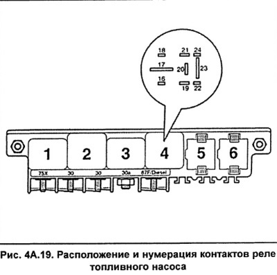
The fuel pump relay is located in the central block, located under the instrument panel on the driver's side. Relay location #4 (see fig. 4A.19).
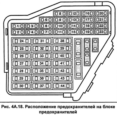
Remove fuse #28 (protects the fuel pump) from the fuse box located at the left end of the instrument panel (see fig. 4A.18).
Connect the LED tester to ground and one of the fuel pump fuse terminals.
To access the relay box, remove the cover on the bottom of the instrument panel on the driver's side.
Turn on the starter, the fuel pump relay should turn on with an audible click and the LED tester should light up.
If the relay does not turn on, check the relay control circuits.
If the relay turns on but the LED tester does not light, connect the tester to a different terminal of the fuse.
If the LED tester does not light again, check the continuity of the circuit between contact 23 of relay 4 (fig. 4A.20) and if the chain breaks, restore it.
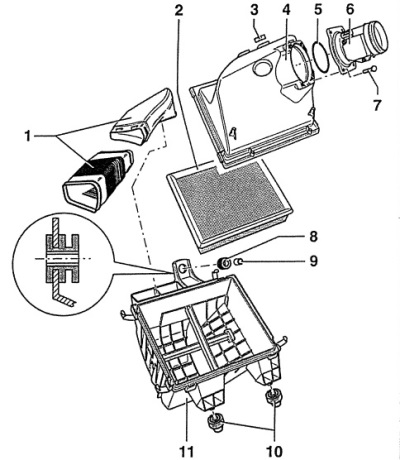
Fig. 4A.20. Air filter
1 - air ducts,
2 - air filter element,
3 - clamp,
4 - air filter cover,
5 - sealing ring,
6 - air flow meter,
7 - bolt, 10 Nm,
8 - rubber bushing,
9 - spacer sleeve,
10 - base,
11 - Air filter housing
If the relay control circuit is OK, then the relay is faulty and needs to be replaced.
Checking the voltage supply
Remove fuel pump relay 4 (Fig. 19) from the central relay block.
Turn on the ignition.
Connect the voltmeter to the following relay base contacts in turn:
- between contact 19 (plus from ignition switch) and "mass";
- between contact 17 (plus battery) and "mass".
The voltmeter should show 12 V (battery voltage). Otherwise, restore the corresponding electrical circuits.
Checking the control circuit
Connect the LED tester between pins 16 (electric motor control regulator) and 17 (plus) relay base (fig. 4A.19).
Turn on the starter, the tester should blink. Otherwise, the relay control circuit is damaged and must be repaired or the electric motor control regulator must be replaced.
Install the fuel pump fuse.
Install the cover on the lower part of the instrument panel on the driver's side.
(The article was copied from the website AUDImanual)