Repair Chevrolet Repair Toyota Repair Honda Repair AvtoVAZ Repair Mercedes-Benz Repair BMW Repair Opel
Home  |  Contacts  |  Sitemap  |    
English Русский
Български
Беларускі
Український
Српски
Hrvatski
Română
Polski
Slovenský
Magyar
AudiManual.ru


  • AUDI 80
  • AUDI 100
  • AUDI A3
  • AUDI A4
  • AUDI A6
  • AUDI A8
  • AUDI Q
  • OTHER
  • ARTICLES
B8 (2007-2015) B7 (2004-2008) B6 (2000-2006) B6 (2000-2006, petrol) B5 (1994-2001) B5 (1994-2001, petrol)

Fuel tank — removal and installation (Audi A4 B5)

  • Home
  • Audi A4
  • B5 (1994-2001)
  • Power unit
  • Fuel injection (gasoline)
  • Fuel tank — removal and installation
            0
Table of contents: Removal ↓ Installation ↓
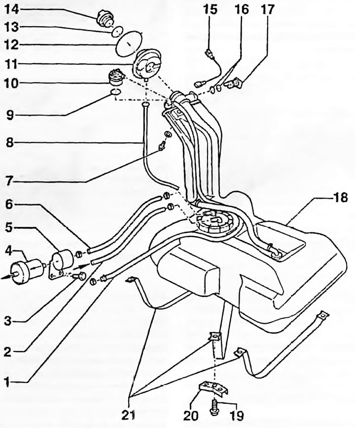
Fig. 8.1. Fuel tank components: 1. Ventilation hose to the carbon adsorber; 2. Return of fuel from…

Fig. 8.1. Fuel tank components: 1. Ventilation hose to the carbon adsorber; 2. Return of fuel from the ramp; 3. Bolt; 4. Fuel filter; 5. Mounting bracket; 6. Fuel supply to the fuel rail; 7. Bolt; 8. Overflow hose; 9. Sealing ring; 10. Valve; 11. Rubber cup; 12. Fastening ring; 13. Gasket; 14. Filler neck; 15. The "mass" wire; 16. Sealing rings; 17. Ventilation valve; 18. Fuel tank; 19. Tank mounting bolts; 20. Bracket; 21. Tank mounting straps


Note: Before starting work, read the warnings in paragraph 7.


Removal


1. Before removing the tank, it is advisable to drain the maximum possible amount of fuel from it. Since there is no drain plug, it is preferable to remove the tank when there is a minimum of fuel left in it. You can drain the fuel using the siphon method into a canister (Fig. 8.1).

2. Disconnect the ground cable from the battery as described in chapter 5A.

3. As described in chapter 11, remove the decorative floor trim in the luggage compartment.

4. Loosen the screws securing the hatch and remove it from the floor.

5. Disconnect the wiring connector from the pump/sensor assembly. Do not disconnect the fuel hoses.


6. Open the filler door and wipe the area around it. Using a screwdriver, gently pry off the rubber cup ring around the filler neck.

7. Remove the rubber cup from the opening in the body.

8. Place chocks under the front wheels, jack up the rear of the car and install safety supports. Remove the right rear wheel.

9. Remove the right rear mudguard.

10. Unscrew the bolt securing the filler neck and protective plate to the body. The bolt also secures the ground wire.

11. If equipped, remove the lower skid plate in front of the rear beam.

12. In front of the tank, attach identification tags to the fuel lines and the evaporative hose of the canister under the bottom. Loosen the clamps and disconnect the hoses. Place a container under the hoses to collect the fuel.

13. Support the tank with a trolley jack, placing a piece of board between them.

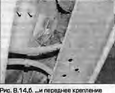
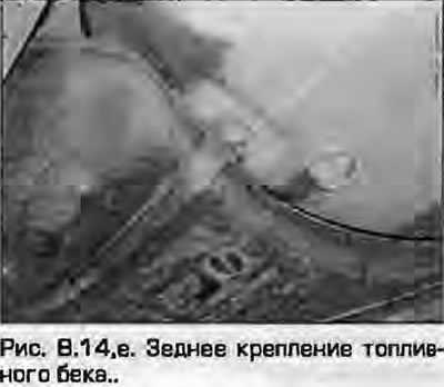
14. Mark the position of the tank mounting straps to ensure correct reinstallation and remove them (fig. 8.14, a, b).3Remember the position of the ground wire on the rear mount.
14. Mark the position of the tank mounting straps to ensure correct reinstallation and remove them…

15. Together with an assistant, lower the tank down and remove it from under the car.


16. If the tank is dirty inside or there is water in it, remove the sensor/pump unit as described in paragraph 7 and flush the tank with clean fuel. The tank is made of plastic; the damaged tank is replaced. However, in some cases minor leaks can be repaired - seek advice from a specialist.

Installation


17. Installation - reverse procedure. Please note the following:
  • a) Make sure that the hoses and wiring are not pinched during reinstallation.
  • b) Properly route and secure all hoses and tubes.
  • c) It is very important to correctly secure the ground wires to the strap and filler neck. Connect an ohmmeter between the metal ring of the filler neck and the open metal part of the body - the ohmmeter should show zero.
  • d) Tighten the strap mounting bolts securely.
  • d) Finally, fill the tank with fuel and check for any signs of leaks before driving on the road.
  • e) Connect the battery as described in chapter 5A.
The article was checked by auto expert Timur Bazhenov
This article is available at russian, bulgarian, belarusian, ukrainian, serbian, croatian, romanian, polish, slovak, hungarian

Share information:
Previous articles
Audi A4 B5: Fuel injection (gasoline)
Next articles

Fuel pump and fuel level indicator sensor unit
Fuel filter — replacement
Simos injection control system components
Bosch Motronic Fuel Injection Control System Components
Fuel injection system — pressure relief
Intake manifold — removal and installation
Fuel injection system — checking and adjustment
Turbocharger — General information, removal and installation


Similar articles on other Audi car models:
Fuel tank — removal and installation Audi 80 B3 (1986-1991, petrol)
Fuel tank — removal and installation Audi 100 C3 (1982-1990, diesel)
Fuel tank, fuel pump and fuel filter Audi A3 Type 8L (1996-2003)
Remote control fuel tank flap Audi A6 C5 (1997-2004)
Fuel expansion tank Audi A8 D2 (1994-2002)
Fuel tank flap emergency release element Audi Q5 Type 8R (2008-2017)
20 liter fuel tank with attachments Audi A2 (1999-2005)
Link to this page in different formats


Visitor comments

No comments yet


How much will 30 + 46 =


A4(B8, 2007-2015) 
  • General information
  • Operating instructions
  • Power unit
  • Petrol engines 1.8 l
  • Petrol engines 1.8/2.0 l
  • Petrol engines 3.0 l
  • Petrol engines 3.2 l
  • Fuel system (petrol)
  • Diesel engines 2.0 l (CA*)
  • Diesel engines 2.0 l (CJCB)
  • Diesel engines 2.7/3.0 l
  • Diesel engines 3.0 l
  • Fuel system (diesel)
  • Transmission
  • Manual gearbox 0B1
  • Manual gearbox 0B2
  • Manual gearbox 0B3
  • Manual gearbox 0B4
  • Automatic transmission 0B5
  • Automatic transmission 0B6
  • Automatic transmission 0AW
  • All-wheel drive system
  • Chassis
  • Front suspension
  • Rear suspension
  • Brake system
  • Steering system
  • Body
  • Exterior
  • Interior
  • Seats
  • Doors, locks and windows
  • Security system
  • Heating and air conditioning
  • Electrical equipment
  • Audio system
  • Power devices
  • Equipment and devices
  • Lighting and lamps
  • Electrical circuits
 
A4(B7, 2004-2008) 
  • General information
  • Introduction to manual
  • Troubleshooting
  • Operating instructions
  • Maintenance
  • Power unit
  • Petrol engines 2.0 (ALT)
  • Petrol engines 2.0 (TFSI)
  • Petrol engines 1.8 (MPI)
  • Diesel engines
  • Cooling system
  • Air conditioner
  • Fuel and exhaust system
  • Ignition system
  • Starting and charging
  • Transmission
  • Clutch
  • Manual gearbox
  • Automatic gearbox
  • Drive shafts
  • Chassis
  • Brake system
  • Front suspension
  • Rear suspension
  • Steering
  • Body
  • Exterior
  • Interior
  • Electrical equipment
  • Equipment and devices
  • Lighting and signaling
  • Windscreen wipers and washers
  • Electrical diagrams
  • Electrical diagrams (since 2007)
 
A4(B6, 2000-2006) 
  • General information
  • Vehicle Description
  • User manual
  • Maintenance
  • Power unit
  • Gasoline engine
  • Diesel engine
  • Lubrication system
  • Cooling system
  • Supply system
  • Injection system
  • Exhaust system
  • Ignition and control
  • Transmission
  • Gear box
  • Clutch and drive shafts
  • Chassis
  • Brake system
  • Car suspension
  • Steering
  • Body
  • Heating and ventilation
  • Exterior (external elements)
  • Interior (internal elements)
  • Electrical equipment
  • Power devices
  • Lighting and appliances
  • Electrical circuits
 
A4(B6, 2000-2006, petrol) 
  • General information
  • Introduction to the guide
  • Car care
  • Power unit
  • Engine repair
  • Lubrication system
  • Cooling system
  • Injection and control system
  • Ignition system
  • Power and exhaust system
  • Transmission
  • Clutch and drive shafts
  • Car gearbox
  • Chassis
  • Suspension and wheels
  • Steering
  • Brake system
  • Body
  • Interior
  • Exterior
  • Electrical equipment
  • Equipment and devices
  • Lighting and signaling
  • Power devices
  • Electrical circuits
 
A4(B5, 1994-2001) 
  • General information
  • Introduction to the guide
  • Car care
  • Maintenance (gasoline)
  • Maintenance (diesel)
  • Power unit
  • Gasoline engines
  • Diesel engines
  • Engine overhaul
  • Cooling system
  • Fuel injection (gasoline)
  • Fuel system (diesel)
  • Exhaust system
  • Ignition system
  • Transmission
  • Clutch
  • Mechanical gearbox
  • Automatic gearbox
  • Drive shafts
  • Chassis
  • Brake system
  • Car suspension
  • Steering
  • Body
  • Exterior
  • Interior
  • Doors, locks and windows
  • Heating and ventilation
  • Electrical equipment
  • Power devices
  • Equipment and devices
  • Electrical circuits
 
A4(B5, 1994-2001, petrol) 
  • General information
  • Vehicle description
  • Maintenance
  • Power unit
  • Engine repair
  • Turbocharging
  • Exhaust system
  • Cooling system
  • Ignition system
  • Fuel system
  • Motronic injection system
  • MPI and MPFI injection system
  • Transmission
  • Clutch
  • Gearbox and shafts
  • Chassis
  • Steering
  • Car suspension
  • Brake system
  • Wheels and tires
  • Body
  • Heating and ventilation
  • Body parts
  • Electrical equipment
  • Fuses and relays
  • Power devices
  • Lighting and lamps
  • Tools and devices
  • Electrical circuits
 
AudiManual.ru © 2017-2026 · Mobile version · Feedback · Sitemap: EN BG BY UA RS HR RO PL SK HU · Site search · News and articles
80 B2 · 80 B3 petrol · 80 B3 · 80 B4 · 100 C3 diesel · 100 C3 petrol · 100 C3 · 100 C4 petrol · 100 C4 · A3 Type 8L · A4 B5 petrol · A4 B5 · A4 B6 petrol · A4 B6 · A4 B7 · A4 B8 · A6 C4 · A6 C5 · A6 C5 Allroad · A8 D2 · Q5 Type 8R · Q7 Typ 4L · Audi A2 ·
This site uses cookies 🍪. Click the button to accept this fact.