
Table of contents: Memory damage ↓ Idle Air Control Switch/Valve ↓ Throttle positioner ↓ Throttle potentiometer ↓ Injector ↓ Throttle Damper (models with manual… ↓
Memory damage
1. The Mono-Jetronic system is equipped with a fault memory for reading coded data. In the event of a fault, a warning light is displayed on the instrument panel.
2. If the engine does not start within six seconds, leave the ignition on. If the engine starts, set the idle mode
3. Connect a good fuse across the contacts of the fuel pump relay being tested for at least five seconds.
4. Remove the fuse, then count the number of flashes given by the warning lamp. If no damage is found, the code 4444 will be issued (four groups of four flash pulses).
5. Reset the code, then repeat the test by connecting and disconnecting the fuse until the code 0000 appears, indicating the end of the test.
6. The decoding of the codes is given in the following table:
- 1111 Control unit
- 1232 Throttle positioner
- 2121 Throttle switch
- 2122 Speed sensor
- 2212 Throttle Potentiometer
- 2312 Coolant Temperature Sensor
- 2322 Intake Air Temperature Sensor
- 2341 Lambda control
- 2342 Lambda sensor
- 2343 Air-Fuel Composition Unit Adjustment Limit, Lean
- 4431 Same as 1232
7. To clear codes 2341 and 2343, disconnect the control module wiring for at least thirty seconds with the ignition off.
8. To reset the fault memory, turn the ignition off, then connect the fuse across the fuel pump relay. Turn the ignition on, wait at least five seconds, then remove the fuse.
Note: Models from 1989 are described in Section 4, Chapter 10.
Idle Air Control Switch/Valve
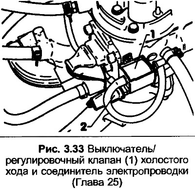
9. Turn on the ignition, then open and close the throttle valve. The control valve should operate twice. If not, disconnect the wiring and connect a diode test lamp across the connector contacts. When the throttle is closed, the test lamp will light up, when the throttle is open, it will go out.
10. Run the engine at idle speed, then disconnect the wiring and reconnect it. The engine speed should increase, then decrease. If not, replace the control valve.
11. Turn off the ignition, then disconnect the wiring from the throttle positioner.
12. Connect the battery voltage and ground wire to the positioner terminals until the plunger has moved fully 2.5 centimeters, then remove the wires.
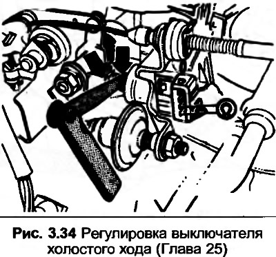
13. Press the plunger to the limiter, then using the feeler gauge, check the gap indicated in Fig. 3.34, it should be 0.5 mm. Adjust the screw nut if necessary.
14. Connect the ohmmeter as shown. With the probe correctly positioned the switch should be open, with the probe removed the switch should be closed (0 ohms).
Throttle positioner
15. With the ignition off, disconnect the wiring from the throttle positioner.
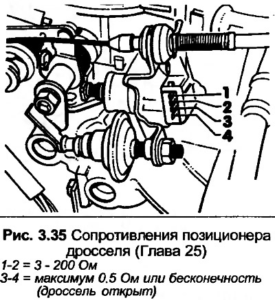
16. Referring to Fig. 3.35 and using an ohmmeter, check the resistance data.
Throttle potentiometer
17. Disconnect the wire contact from the potentiometer.
18. Referring to Fig. 3.35 and using an ohmmeter, check the resistance data. When checking between terminals 1 and 2, the resistance will change during the first quarter of the throttle opening, then remain constant. Between terminals 1 and 4, the resistance will be constant during the first quarter of the throttle opening, then begin to change.
Injector
19. Start the engine and warm it up to operating temperature, then remove the air filter.
20. With the engine idling, check that the "cone" of aerosol sprayed onto the throttle valve is even. Increase the engine speed to 3000 rpm, then quickly close the throttle. The injector should close briefly, indicating that the engine braking system is functioning correctly.
21. With the ignition off, check that the injector does not leak more than two drops per minute.
22. Remove the inlet elbow from the pump section.
23. Turn on the starter and check that the injector is visible on the throttle valve. If not, disconnect the injector wiring and use an ohmmeter to check that the injector resistance is 1.2-1.6 Ohms at an ambient temperature of 15-30°C.
24. Connect the LED test lamp to the center terminal, then turn on the starter. The test lamp should flicker, indicating that there is current to the injector.
Throttle Damper (models with manual transmission)
25. Check that with the throttle closed, the lever extends the plunger into the shock absorber at least 4.0 mm. If not, loosen the mounting nut and adjust the shock absorber so that the lever just touches the plunger. From this position, rotate the shock absorber 4 and 1/4 turns toward the lever, then tighten the nut.