
Table of contents: Memory damage ↓ Lambda sensor ↓ System control ↓ Coolant temperature sensor (models… ↓ Throttle potentiometer ↓ Throttle switch ↓ Idle switch ↓ Air volume sensor ↓ Coolant temperature sensor (models… ↓
Memory damage
1. The multi-point injection (MPI) system is equipped with a fault memory common to the fuel injection system and the ignition system. The self-test procedure is described in Section 4, Chapter 12.
Lambda sensor
2. Disconnect the wire contact located behind the intake manifold (Fig. 3.38) and connect the voltmeter to the two clamps in the connector.
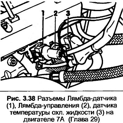
3. Start the engine, make sure the voltage is 12 volts. If not, check the circuit.
4. If the Lambda sensor was removed from the exhaust manifold, then before installation its threads must be coated with the appropriate paste.
System control
5. The MPI control unit includes a sequential test function to check the fuel pump relay, individual injectors, idle speed control valve and carbon canister. A special unit is required to read the damage data, so this work should be entrusted to an Audi dealer. Since the tests were carried out with the engine off, the operation of each individual component can be heard.
Coolant temperature sensor (models before 1988)
6. If the coolant temperature is above 20°C, disconnect the contact of wire "3", shown in Fig. 3.38.
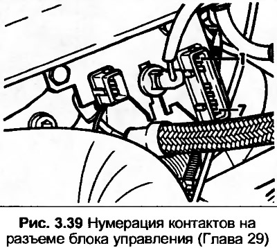
7. Connect an ohmmeter between contacts 6 and 7 on the connector (Fig. 3.39), the resistance should be approximately 2400 Ohms. If not, check the wire contact on the sensor.
Throttle potentiometer
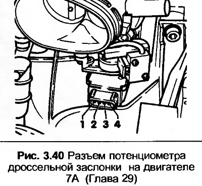
8. Disconnect the wire contact from the throttle body housing.
9. With the ignition on, connect a voltmeter to terminals 2 and 4, then 3 and 4, in both cases the voltmeter should show 5 volts. If not, check the wiring between the yellow connector of the control unit and the connector with four pins.
10. To check the potentiometer, disconnect the wire contact and remove the air intake elbow.
11. Connect an ohmmeter between pins 2 and 4, the resistance should be 3500-6500 ohms. Between pins 2 and 3, the resistance should be 3000-6000 ohms. Fully open the throttle, the resistance should be 0-600 ohms.
Throttle switch
12. Disconnect the wiring and connect an ohmmeter between terminals 1 and 2 on pre-January 1989 models, or 3 and 4 on January 1989 and later models.
13. Loosen the switch mounting screws and adjust the position so that a 0.75mm thick feeler gauge fits between the main installation screw and the limiter at the switch opening point. Tighten the screws.
Idle switch
14. Disconnect the wiring and connect an ohmmeter between the two contacts on the switch.
15. Insert a 0.5mm feeler gauge between the main installation screw and the limiter. The resistance should be infinite. Pull the feeler gauge out and check that the throttle valve closes. The resistance should be zero.
Air volume sensor
16. Disconnect the wiring from the air volume sensor, connect a voltmeter between contact 3 and engine ground.
17. Turn on the ignition, the voltmeter should show 12 volts. If not, check the wiring.
18. Connect a voltmeter between pins 3 and 2, the voltmeter should show 12 volts.
19. Connect a voltmeter between pins 2 and 4, the voltmeter should show 8 volts.
20. Reconnect the connector, pull back the rubber shell.
21. Turn on the ignition and connect a voltmeter between contacts 2 and 4. The voltmeter should show approximately 1.0-7.5 volts. Between contacts 2 and 1 the voltage should be 0.3-1.1 volts.
22. Turn off all additional electrical equipment, start the engine and vary the speed between idle and 4000 rpm. The voltage should be 1.5-3.4 volts.
Coolant temperature sensor (models since 1989)
23. Make sure the engine has cooled to room temperature.
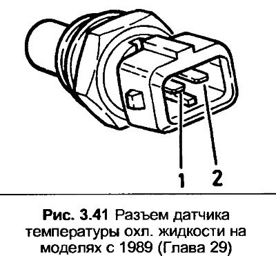
24. Disconnect the wiring and connect an ohmmeter between terminals 1 and 2 as shown in Fig. 3.41. The resistance should be approximately 2500 ohms with a coolant temperature of 20°C. If it is not possible to cool the engine, the resistance should be approximately 330 ohms with a coolant temperature of 80°C.
[Content source: the specified website AUDIMANUAL]