
Table of contents: Adjustment conditions ↓ DX Engine ↓ RM Engine ↓ PS (since 1989) and JN engines ↓ NG Engine ↓ PS engine (before 1989) and KV ↓ Engine ZA ↓ Engine 7A ↓
Adjustment conditions
1. The engine must be warmed up to operating temperature.
2. All electrical components must be turned off, the radiator cooling fan must not operate during adjustment.
3. The exhaust system must be in good condition.
4. The ignition timing angle must be set correctly.
5. Where used, Lambda control must work correctly.
6. On models with automatic transmission, the kickdown function must work correctly.
7. If the injector pipes are disconnected, the engine should be accelerated to 3000 rpm and back to idle several times for at least two minutes before making changes.
8. Air conditioning system (where is it used) must be turned off.
9. Where used, remove the plug from the carbon filter adjustment screw.
10. The throttle valve should be in the idle position.
DX Engine
11. Install the clamp to the idle speed control unit hose (Fig. 3.19).
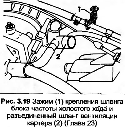
12. Disconnect the crankcase ventilation hose from the valve cover and route it to fresh air.
13. With the ignition off, connect the tachometer and exhaust gas analyzer to the engine.
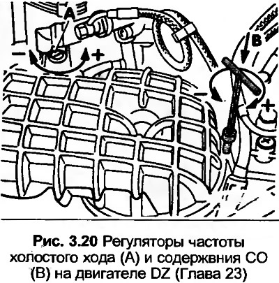
14. Start the engine, then check that the idle speed and CO content are as per Specifications. If necessary, adjust the screws shown in Fig. 3.20 using the special CO content adjustment key. When adjusting the CO, do not press the key or rotate the engine with the adjusting key installed.
15. Guided by Chapter 16, paragraph 7, connect the crankcase ventilation hose.
RM Engine
16. With the ignition off, connect the tachometer and exhaust gas analyzer to the engine.
17. No adjustment is possible. If the parameters are incorrect, check all vacuum connections and the gray winding of the frequency valve. If necessary, output the damage memory.
PS (since 1989) and JN engines
18. See points 11-15, but connect the exhaust gas analyzer with a measuring pipe in front of the exhaust manifold.
NG Engine
19. With the ignition off, connect the tachometer to the engine and the measuring tube of the exhaust gas CO analyzer.
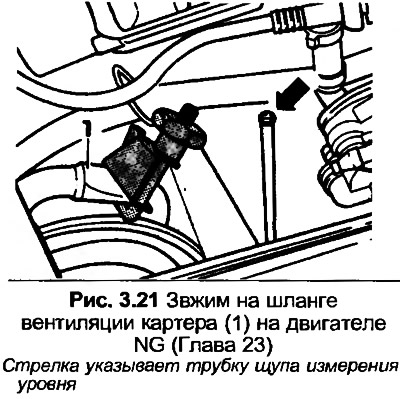
20. Install the clamp on the crankcase ventilation hose (Fig. 3.21). Remove the dipstick and cover the tube with a rag.
21. Start the engine, then check that the idle speed and CO content are as specified Specifications.
22. Note that the idle speed cannot be adjusted and the screw in the throttle body must be fully screwed in.
23. Check the ignition timing as described in Section 4.
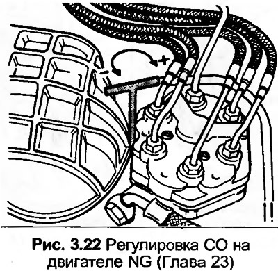
24. Disconnect the electrical wiring from the Lambda sensor, then check the CO content. If necessary, use a special key to adjust the ignition timing (Fig. 3.22).
25. Connect the wiring to the Lambda sensor and check the CO content.
26. Disconnect the carbon filter line, the CO content should drop. Now pinch the line, the CO content should increase and immediately drop. If not, check the Lambda sensor.
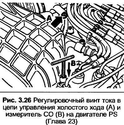
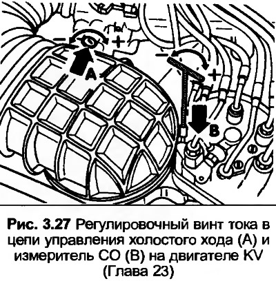
PS engine (before 1989) and KV
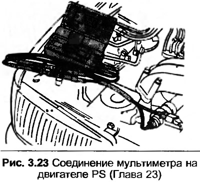
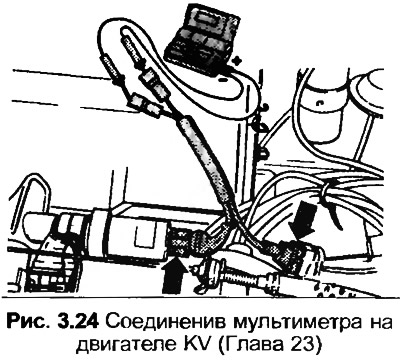
27. With the ignition off, connect the tachometer and exhaust gas analyzer to the engine. Also connect the multimeter to the idle speed stabilization unit (photo), referring to Fig. 3.23 and 3.24.
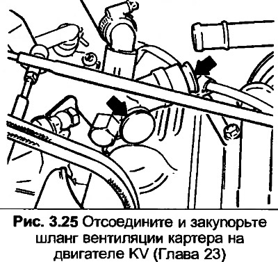
28. On the KV engine, disconnect and plug the crankcase ventilation hose.
29. On the PS engine, install the clamp on the crankcase ventilation hose, then remove the dipstick and cover the tube with a rag.
30. Start the engine and set it to idle mode.
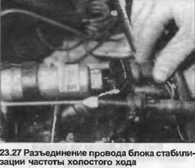
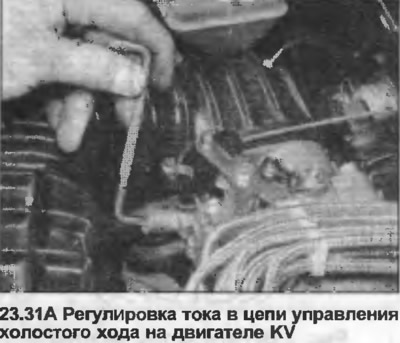
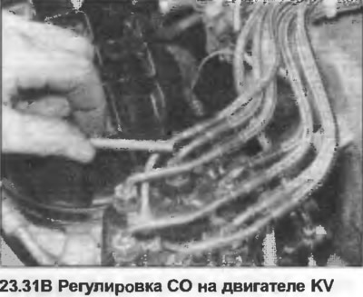
31. Check that the control circuit current and CO content correspond to the data in the Specifications. If necessary, adjust the screws shown in Fig. 3.26 and 3.27 (photo). If the control circuit current remains constant, approximately 470 mA, check the stabilization of the idle speed.
32. See paragraphs 14 and 15.
Engine ZA
33. Check the ignition timing as described in Section 4.
34. With the ignition off, connect the tachometer to the engine. Also connect the exhaust gas analyzer to the measuring tube on the exhaust manifold.
35. Start the engine and set it to idle speed. Check the idle speed as given in Specifications.
36. On models with air conditioning, the idle speed should increase by approximately 70 rpm when the air conditioning is on.
37. Check CO content as defined Specification. If adjustment is necessary, remove the carbon canister cover and disconnect the crankcase ventilation hose from the valve cover.
38. With the ignition off, disconnect the wiring from the differential pressure regulator and connect a multimeter using an adapter. Turn on the ignition and check that the current in the control circuit is positive. If not, replace the wiring.
39. Start the engine and set it to idle mode.
40. Adjust the CO screw using the special key until the current in the control circuit is between 0 and 5 mA. When adjusting the CO, do not press the key or rotate the engine with the adjusting key installed. After removing the key, accelerate the engine before checking the CO content.
41. If necessary, clear the damage memory.
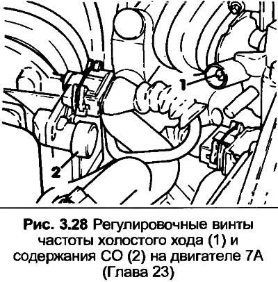
Engine 7A
42. With the ignition off, connect the tachometer and exhaust gas analyzer to the engine.
43. Install a clamp to the crankcase ventilation hose located behind the fuel pressure regulator. Remove the dipstick and cover the tube with a rag.
44. Start the engine and set it to idle mode.
45. Remove the cover from the fuse box and connect the fuse across the fuel pump relay contacts. Wait approximately three seconds, then check that the idle speed is as per Specifications. If necessary, adjust the idle speed screw shown in Fig. 3.28.
46. Check the CO content as given in Specifications and adjust the screw if necessary.
47. After installing the CO, adjust the idle speed.
48. Remove the fuse from the fuel pump relay and increase the engine speed to 2000 rpm. If the idle speed and CO data now differ from Specifications, identify the faulty component using the vehicle's self-diagnosis system.