
Table of contents: Increased idle speed ↓ Engine Brake Block Valve (Keihin I) ↓ Engine Brake Block Valve (Keihin II) ↓ Basic installation of the throttle… ↓ Clearance of the locking lever of… ↓ Accelerator pump performance ↓ Throttle channel heating (Keihin II) ↓ Block of exit beyond the set limits… ↓ Throttle positioner ↓ Voltage of the control valve ↓ Control valve ↓ Increased idle speed (models with… ↓
Increased idle speed
1. Connect the tachometer to the engine. Warm up the engine to operating temperature.
2. Remove the air filter and plug the vacuum hose to control the air temperature.
3. The automatic air damper must be fully open.
4. Using a screwdriver, fully open the choke on the carburetor, but leave the choke lever in its original position.
5. Start the engine and check the fast idle speed, compare with the data in Specifications. Adjust the coupling lever if necessary.
Engine Brake Block Valve (Keihin I)
6. Open the air damper control fully.
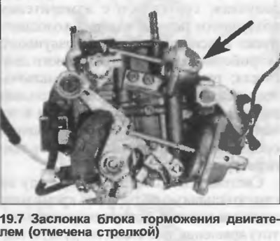
7. Create a vacuum of 400 mBar in the engine brake block (photo), then use a drill to check that the clearance between the lower edge of the choke and the carburetor wall corresponds to the data in the Specifications. If necessary, adjust the control lever.
Engine Brake Block Valve (Keihin II)
8. Open the air damper control fully.
9. Press the linkage rod in the engine brake unit, then use a drill to check that the clearance between the lower edge of the air damper and the carburetor wall corresponds to the data in the Specifications. If necessary, adjust the control lever.
10. The engine brake unit can be checked after removing the tappet and vacuum seal. If the tappet and inner diaphragm are defective, replace them.
Basic installation of the throttle valve chamber 2
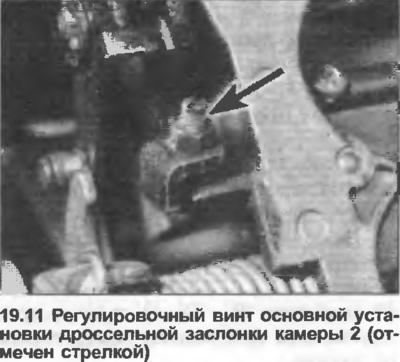
11. The adjusting screw (photo) is set at the factory and normally does not require adjustment. If the adjustment has been disturbed, perform the following procedures.
12. With the carburetor removed, fully open the throttle of chamber 2, leaving the throttle of chamber 1 closed.
13. Loosen the nut and back off the adjusting screw so that there is a gap between the lever and the stopper, then turn the screw clockwise until it touches the stopper. Then turn the screw three-quarters of a turn clockwise. Then tighten the screw using thread locking fluid.
14. Check the idle speed after adjustment.
Clearance of the locking lever of the chamber 2 (Keihin II)
15. With the carburetor removed, fully open the throttle so that the throttle valve is closed.
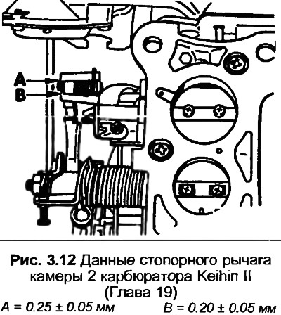
16. Referring to Fig. 3.12, check that the installation is correct. If not, adjust as required. Install the new plug in place.
Accelerator pump performance
17. With the carburetor removed, fill the float chamber with fuel to the correct level and check the carburetor over a calibrated container.
18. Open the valve completely. Close the throttle valve of chamber 1 completely by unscrewing the screw.
19. On the Keihin II carburetor, check that the accelerator pump lever touches the plunger - no gap is allowed.
20. Open the throttle lever slowly and fully ten times, performing each movement for at least three seconds.
21. Measure the amount of fuel poured out in ten strokes and compare it with the amount given in the Specifications. Adjust the limiter if necessary.
Throttle channel heating (Keihin II)
22. Unscrew the heating element and turn on the ignition.
23. Connect the LED test lamp between the yellow/black wire and the carburetor body. The lamp should light.
24. Connect the test lamp between the heating element housing and the carburetor housing. The test lamp should light.
Block of exit beyond the set limits (models with manual transmission)
25. Warm up the engine to operating temperature, then turn it off.
26. Connect the tachometer to the engine.
27. Start the engine, increase the speed to 4000 rpm, then release the engine. The engine speed should slowly decrease to 1800 rpm, then quickly drop to idle speed. If not, check:
- (a) Throttle positioner
- (b) Voltage for the control valve
- (c) Control valve
Throttle positioner
28. The throttle valve positioner is located below the engine brake valve. With the engine at normal operating temperature, connect a vacuum pump to the positioner and create 350 mBar (Keihin I) or 400 mBar (Keihin II).
29. The engine speed should be 1200-1250 rpm. If not, adjust the provided screw.
30. Check vacuum pipes for leaks.
Voltage of the control valve
31. Warm up the engine to operating temperature, then turn it off.
32. Connect the tachometer to the engine.
33. Disconnect the connector from the control valve, connect the voltmeter to the two clamps in the connector.
34. Start the engine at idle speed. The voltmeter should show battery voltage. If not, check the battery voltage using the black wire on the connector. Similarly, connect the voltmeter between the brown/red wire and the positive terminal of the battery. No voltage indicates a break in the wiring.
35. Slowly increase and then decrease the engine speed, checking the switching of the control unit with a voltmeter connected across the two clamps. At a speed of more than 1900 rpm, the voltmeter should show zero, but at a speed of less than 1750 rpm, it should show battery voltage. Replace the control unit if necessary.
Control valve
36. Remove the air filter, then start the engine at idle speed.
37. Disconnect the control valve wiring and remove the vacuum tube.
38. On the Keihin I carburetor, disconnect the vacuum hose from the brake booster hose.
39. Remove the control valve breather cap and attach a piece of hose to the control valve. Blow into the hose and check that it is closed.
40. Connect the wiring to the valve and blow into the hose. The valve should let air through.
41. On the vacuum chamber side, the valve must always be open.
Increased idle speed (models with automatic transmission)
42. Warm up the engine to operating temperature, then turn it off.
43. Connect the tachometer to the engine.
44. Tighten the handbrake well, then start the engine at idle speed.
45. Turn on the rear window heating, high beam headlights and heater fan to maximum speed.
46 Press the brake pedal and select the "D" position. In this position, the throttle positioner should open the throttle slightly. If not, check the vacuum chamber for leaks and check the control valve as follows.
47. Disconnect the right wiring from the control valve and connect the test lamp to the clamps in the connector.
48. Turn on the ignition and select position "N". The indicator lamp should light.
49. Select "R", "D", "2" and "1", in these positions the control lamp should not light.
50. Check the control valve as described in paragraphs 38-41 inclusive.