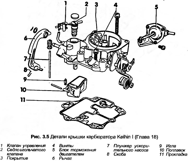
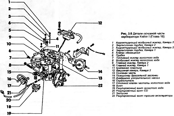
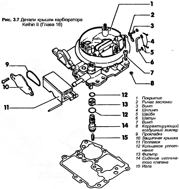
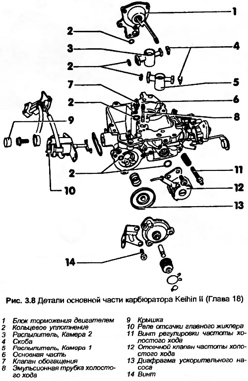
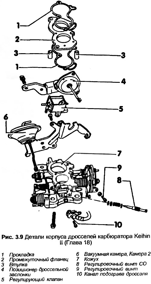
Note: The following steps describe procedures for the Keihin I carburetor. Procedures for the Keihin II carburetor are similar, but refer to Figures 3.5-3.9
1. With the carburetor removed from the engine, clean the outside surface.
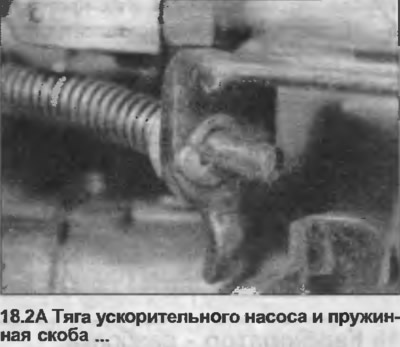
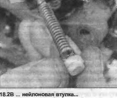
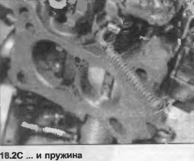
2. Disconnect the accelerator pump rod, remove the spring clip, separate the rod and remove the nylon bushing with the spring (photo).
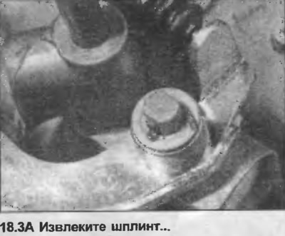
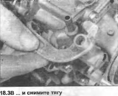
3. Remove the cotter pin and remove the washer with the rod (photo).
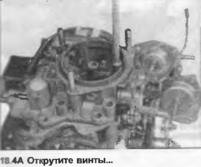
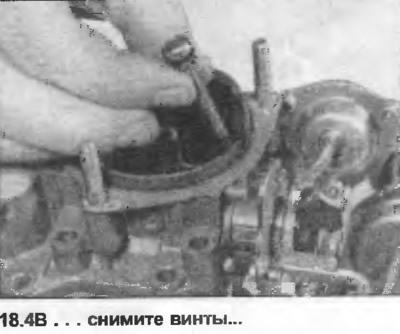
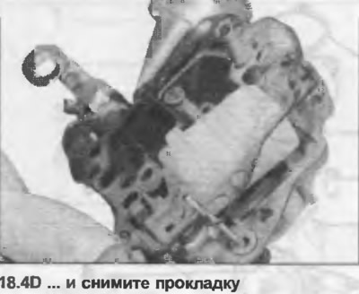
4. Unscrew the screws. Remove the gasket (photo).
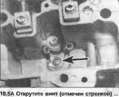
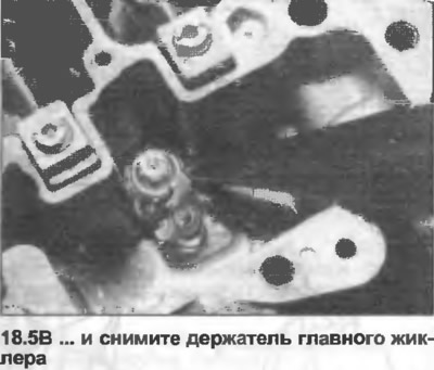
5. Unscrew the screw from the base of the float chamber and remove the main jet holder (photo).
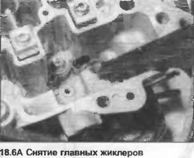
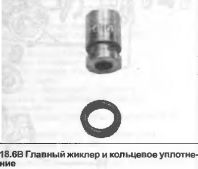
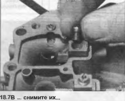
6. Carefully remove the main jets. If necessary, remove the O-ring (photo).
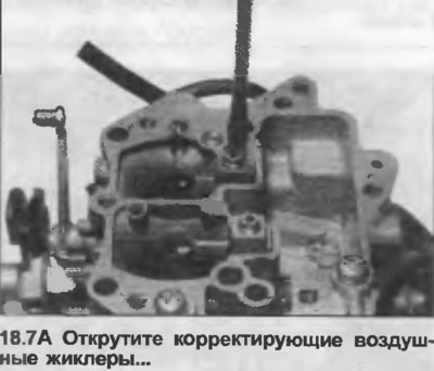
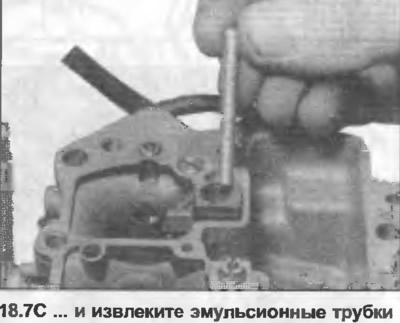
7. Unscrew and remove the correcting air jets and emulsion tubes (photo).
8. Unscrew the enrichment valve from the base of the float chamber.
9. Unscrew the idle air jet, then unscrew the plug and remove the idle fuel jet.
10. Press out the float pivot pin and remove the float with the needle valve. Disconnect the valve.
11. Disassemble the carburetor only for cleaning. Clean all parts with fuel and, if possible, blow them out with compressed air. Do not clean the jets and holes with a wire. Check the needle valve and float for wear. Replace them if necessary.
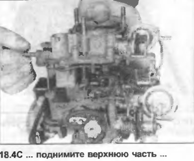
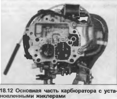
12. Assembly is carried out in the reverse order (photo). Before installing the upper part, check that the upper position of the float corresponds to the data in Specifications.
13. Referring to Fig. 3.10 or 3.11, clamp the cover at a 60° angle so that the needle valve is closed and the spring pin is not clamped.
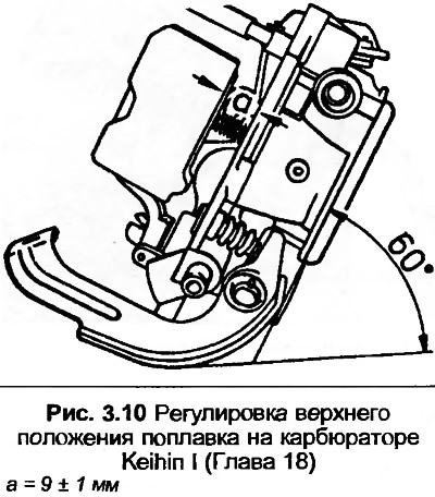
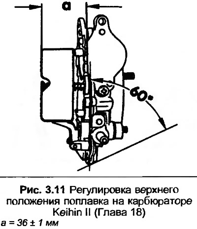
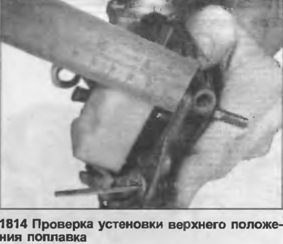
14. Measure the distance between the top of the float and the cover (without gasket), using a steel ruler (photo). If adjustment is necessary, remove the plug from the cover and move the needle valve as required.
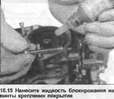
15. Before installing the cover mounting screws, apply thread locking fluid (photo) to the threads and lubricate all connections with molybdenum grease.