
Table of contents: Idle Speed Block (dZ engine) ↓ Air flow meter plate ↓ Cold start valve and fuel injection… ↓ Cold Acceleration Enrichment ↓ Diaphragm pressure sensor ↓ Throttle switch ↓ Auxiliary pneumatic valve ↓ Warm-up valve ↓ Basic throttle valve installation ↓
Idle Speed Block (dZ engine)
1. Two-way valve 1 (Fig. 3.29) increases the engine speed when it falls below 700 rpm. The control unit is located under the panel.
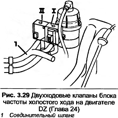
2. Two-way valve II increases engine speed when the air conditioner is on.
3. To check the check valve I, reduce the engine speed with the adjustment screw and check that the engine speed increases when it drops below 700 rpm. Now squeeze the hose 1 (Fig. 3.29) and check the drop in engine speed.
4. With the hose pinched, adjust the idle speed to the specified value, then release the hose. This will cause the engine speed to increase to 1050 rpm, the valve will close, and the speed will drop to normal idle speed.
5. To test check valve II, run the engine at idle, then squeeze the hose. The engine speed should not change. Turn on the air conditioner and repeat the test. This time the engine speed should decrease.
Air flow meter plate
6. Remove the air duct from the air flow meter. Disconnect the high-tension wire from the ignition coil and ground it, operate the starter for ten seconds.
7. Lift the plate and check that it has equal resistance throughout the full range of motion.
8. Check the dimension shown in Fig. 3.30. If necessary, the position can be adjusted by bending the wiring brackets under the plate.
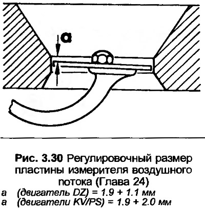
9. The plate free play should be 0.5-3.0 mm on the DZ engine, and on the KV/PS engines the free play should be a maximum of 2.1 mm.
Cold start valve and fuel injection mode switch
10. Disconnect the high-tension wire from the ignition coil and ground it.
11. Disconnect the wiring from the cold start valve and connect the LED indicator lamp to the clamps in the connector.
12. Disconnect the wiring from the fuel injection mode switch and ground the green/white wire clamp. Do not ground the red/black wire clamp.
13. Turn on the starter, the indicator lamp should light up.
14. Install the connector to the switch, leaving the green/white wire grounded.
15. Remove the cold start valve and point it into a glass cup. Turn on the starter, the fuel from the valve should spray out in the form of an even cone.
16. Wipe the valve dry.
17. With the cold start valve in place but the wiring disconnected, connect the LED test light across the two connector terminals.
18. Turn on the starter for ten seconds, the control lamp should light for one to eight seconds, depending on the coolant temperature (for testing, the maximum temperature is 30°C).
Cold Acceleration Enrichment
19. Cold Boost Enrichment operates when the fuel injection mode switch, diaphragm pressure sensor and throttle switch are closed.
20. Perform the procedure described in points 11 and 12, then start the engine and set it to idle mode. The indicator lamp should not light.
21. Quickly open the throttle, the control lamp should light briefly (by 0.4 seconds).
Diaphragm pressure sensor
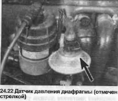
22. Disconnect the electrical wiring from the pressure sensor (photo).
23. Start the engine and set it to idle mode.
24. Connect an ohmmeter to the two terminals on the switch (photo), the resistance should be infinite, indicating that the contacts are open.
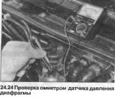
25. Quickly open the throttle, the resistance should drop briefly.
Throttle switch
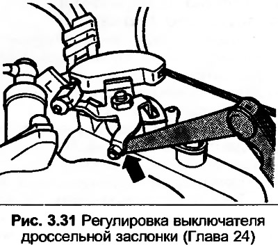
26. Disconnect the wire contact from the throttle switch and connect an ohmmeter to the two clamps.
27. With the throttle closed, the resistance should be infinite.
28. Slowly open the throttle until you hear the switch contacts operate. At this point, the resistance should be infinite and the gap between the idle speed limiter and the throttle lever should be 0.2-0.6 mm. Adjust the switch if necessary.
Auxiliary pneumatic valve
29. Disconnect the high-tension wire from the ignition coil and ground it.
30. Disconnect the wiring contact from the auxiliary pneumatic valve and connect the LED test lamp across the connector contacts.
31. Turn on the starter, the indicator lamp should light.
32. Turn off the ignition and connect the tachometer.
33. Start the engine and set it to idle mode.
34. Compress the hose between the auxiliary air valve and the intake manifold. The engine speed should decrease.
35. Reconnect the wiring and repeat the test with the engine warm. The engine speed should not change.
Warm-up valve
36. Disconnect the high-tension wire from the ignition coil and ground it.
37. Disconnect the wiring from the heating valve, connect the LED indicator lamp across the connector contacts.
38. Turn on the starter, the indicator lamp should light up.
Basic throttle valve installation
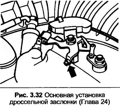
39. The adjusting screw is set at the factory and normally does not require adjustment. If the adjustment has been lost, perform the following procedure.
40. Loosen the nut, back off the adjusting screw so that there is a gap between the screw and the stopper, then turn the screw clockwise until it touches the stopper. The point of contact is best fixed using a piece of thin paper placed between them. From this point, turn the screw further by half a turn. Apply locking fluid to the threads of the nut, then tighten the nut, preventing the screw from turning.
41. Check the idle speed setting values after adjustment.
[The text is based on materials from the website: AudiManual.ru]