



Table of contents: Memory damage ↓ Lambda control ↓ Enriching the Launch ↓ Engine braking ↓ Cold start valve ↓ Air flow meter plate ↓ Throttle switches ↓ Basic throttle valve installation ↓
Memory damage
1. The KE-Motronic system is equipped with a fault memory common to the fuel injection system and the ignition system. The self-test procedure is described in Section 4. Chapter 10.
Lambda control
2. Connect the digital multimeter to the differential pressure controller.
3. Start the engine and let it idle for two minutes.
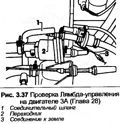
4. Measure the current in the control circuit, then disconnect hose 1, shown in Fig. 3.37. The current in the control circuit should increase. If not, disconnect the Lambda sensor wires and ground the green wire clamp for approximately twenty seconds. If the current in the control circuit now changes, the Lambda sensor is faulty.
Enriching the Launch
5. Connect the digital multimeter to the differential pressure controller.
6. Disconnect the high tension wire contact from the ignition coil.
7. Remove fuse No.13.
8. Turn on the starter, the current in the control circuit will decrease to 35-45 A within three seconds, then drop to 0.
Engine braking
9. Connect the digital multimeter to the differential pressure controller.
10. Turn on the ignition and measure the current in the control circuit.
11. Start the engine and increase the speed to more than 3000 rpm.
12. Quickly close the throttle, the current in the control circuit will briefly become negative.
Cold start valve
13. Disconnect the high tension wire contact from the ignition coil.
14. Disconnect the wiring from the temperature sensor and connect a 15K resistor in series with the disconnect.
15. Remove the cold start valve and place it over the measuring cylinder.
16. Turn on the starter, a smooth cone-shaped stream should spray out of the valve for eight seconds.
17. Wipe the valve and let it dry for 1 minute.
18. Disconnect the wiring, connect the ohmmeter to the valve clamps. The ohmmeter should show 10 ohms.
Air flow meter plate
19. Be guided Chapter 24, paragraphs 6-9.
Throttle switches
20. The inspection requires the use of special tools, therefore, leave this work to your Audi dealer.
Basic throttle valve installation
21. Be guided Chapter 24, paragraphs 39-41.