
Table of contents: Self-control system ↓ Ignition coil ↓ MPI control unit ↓ Ignition Timing Sensor ↓ Hall sensor ↓
Warning: Before disconnecting any electrical wiring (including high voltage) from the ignition system, the ignition must always be switched off. Failure to observe this precaution may result in damage to the integrated circuit components and electric shock.
Self-control system
1. The procedures for pre-1989 models are the same as for the FEI system described in Chapter 8. The decoding of the codes is as follows.
- 1111 MPI Control Unit
- 2111 Engine Speed Sensor (Gray)
- 2112 Ignition Timing Sensor (Black)
- 2113 Hall sensor
- 2114 Distributor adjustment
- 2121 Idle switch
- 2141 or 2143 Knock sensor or low octane fuel
- 2142 or 2144 Knock Sensor
- 2212 Throttle Potentiometer
- 2242 Air volume sensor, CO potentiometer
- 2232 Air Volume Sensor (G70)
- 2233 Air volume sensor (G19)
- 2234 Battery voltage
- 2312 Coolant Temperature Sensor
- 2342 Lambda sensor
- 4431 Idle speed control, stabilizing valve
- 4444 No damage
- 0000 End of fault indication
2. The procedures for models from 1989 are the same as for the Motronic system described in Chapter 10. The decoding of the codes is the same as in paragraph 1 of this Chapter.
Ignition coil
3. Disconnect the wiring from the power output block.
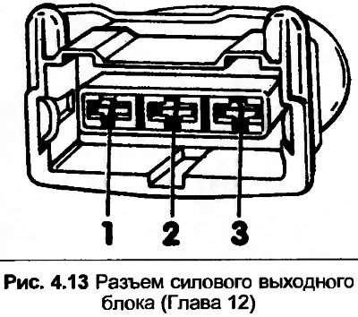
4. Connect the voltmeter between terminal 1 on the connector and the grounded wire. Turn on the ignition, the device should show 12 volts.
5. Repeat the test by connecting the meter between terminals 1 and 3. If there is no reading, check the wiring.
6. Connect the voltmeter between terminals 2 and 3, then quickly rotate the engine with the starter. The device should show at least 0.2 volts.
7. If not, remove the glove box, disconnect the MPI control unit and disconnect the multi-pin plug (black). Using an ohmmeter, check the resistance between terminal 2 on the amplifier unit connector and terminal 9 on the multi-pin plug.
8. Check the wiring between the amplifier unit and the ignition coil and between the amplifier unit and the engine.
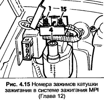
9. Disconnect the high tension wires from the ignition coil and the connector from the amplifier unit. Disconnect the clamp cover.
10. Connect an ohmmeter between the high-voltage clamp and clamp 1(-). The resistance should be 5000-9000 ohms.
11. Connect the ohmmeter between terminals 1(-) and 15(+). The resistance should be 0.5-1.5 Ohm.
12. Replace the ignition coil and amplifier unit if the data is not correct.
MPI control unit
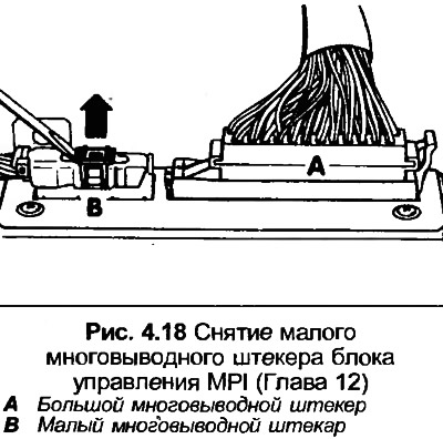
13. Remove the glove box, disconnect the MPI control unit and disconnect the black multi-pin plug.
14. Turn on the ignition, then connect the voltmeter in turn to terminals 25 and 1, 25 and 2, 25 and 13, and 25 and 21 on the multi-wire plug. The device should show 12 volts in each case.
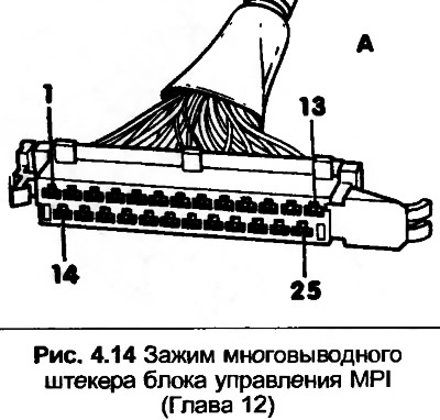
15. Turn off the ignition, reconnect the connector, then turn on the ignition.
16. Connect a voltmeter between terminals 18 and 1, the device should show 12 volts. If not, check the wiring or replace the control unit.
Ignition Timing Sensor
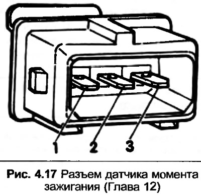
17. Locate the black connector and socket on the left side of the engine compartment bulkhead, disconnect the connector and remove it from the suspension.
18. Connect an ohmmeter between terminals 1 and 2 on the connector, the resistance should be 1000 ohms.
19. Connect the ohmmeter alternately to terminals 1 and 3, and 2 and 3, the device should show infinity.
20. Check the associated electrical wiring.
21. Remove the black bracket and disconnect the small multi-pin plug from the control unit. The contact pins should be in good condition.
Hall sensor
22. Disconnect the high-voltage wiring from the breaker-distributor cover and ground it.
23. Disconnect the connector from the Hall sensor distributor and connect a voltmeter between the two outer terminals on the connector.
24. Turn on the ignition, the voltmeter should show 9 volts. If not, check the wiring.
25. Reconnect the connector.
26. Connect the voltmeter between terminals 1 and 2.
27. Remove the distributor cover, then turn the engine until the distributor rotor aligns with the TDC mark (Chapter 3, and also Fig. 4.21).
28. The voltmeter should show 4 volts.
29. Turn the engine until ignition occurs, the voltmeter should show 0-0.5 volts.
30. If the data is incorrect, check the wiring. Replace the Hall sensor if necessary.
[The full version is posted on the resource: Audimanual.ru]