
Table of contents: Self-control system ↓ Ignition coil ↓ FEI Control Unit ↓ Distributor Hall Sensor ↓ Power output block ↓ FEI Control Unit Multi-Pin Plug ↓
Warning: Before disconnecting any wires (including high voltage) in the ignition system, the ignition must always be turned off. Failure to do so may result in damage to the integrated circuit components and electric shock.
Self-control system
1. The FEI control unit is equipped with a fault memory that only functions when the ignition is on. The fault memory is erased when the ignition is turned off. If a fault occurs that could cause engine damage, a warning light on the instrument panel will light. The light should light whenever the ignition is on and go out when the engine is started. If this does not happen, there is probably a fault in the engine electrical circuit. However, what can happen if the fuel has too low an octane number, as the knock sensor will be continuously activated at the control limit.
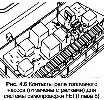
2. If the warning light does not illuminate, remove the fuse box cover and connect a known good fuse across the fuel pump relay terminals. The light should illuminate as long as the fuse is connected. If not, check the wiring for continuity.
3. First check fuses 13, 24 and 28 and the warning light for proper operation. Also check the ground wire of the intake manifold. Disconnect the air conditioner (if installed), then turn on the ignition.
4. Start the engine and warm up the car for at least five minutes, during which the engine speed should exceed 3000 rpm several times and the accelerator pedal should be fully depressed briefly.
5. Run the engine at idle speed. Do not increase the engine speed during the following tests.
6. Connect a known good fuse across the fuel pump relay test contacts for at least four seconds.
7. Remove the fuse, then count the number of flashes given by the warning lamp. The sequence starts with a signal lasting 2.5 seconds and a pause lasting 2.5 seconds, then pulses are given after 0.5 seconds. Count each group of signals and the result will be a four-digit number, followed by four signals of 2.5 seconds. The pause will indicate the end of the fault warning signal. If no fault is found, the code 4444 will be given (four groups of four).
8. Check the amount of damage by repeating the procedure from point 6.
9. Control unit KE III-Jetronic (nG engine) the damage memory can be viewed in the same way. For details, see Section 3.
10. Explanations of the NG engine codes are given in the following table.
- 1111 Control unit
- 2121 Throttle Switch I
- 2122 Speed signal from FEI control unit
- 2123 Throttle Switch II
- 2141 Knock Control at Limit
- 2142 Knock Sensor
- 2223 Altitude sensor
- 2232 Air flow meter potentiometer or KE III control unit signal
- 2233 Voltage for load and altitude signals from the KE III control unit
- 2312 Coolant Temperature Sensor
- 4431 Idle Speed Stabilization Valve
- 4444 No damage detected
- 0000 Code Completion
11. Explanations of the displayed codes for the PS engine are given in the following table.
- 2141 Knock Control Limit
- 2142 Knock sensor defective
- 2222 FEI control unit pressure sensor defective or throttle valve switch II defective
- 2221 Defective intake manifold vacuum hose going to FEI control unit
- 2312 Coolant Temperature Sensor
- 4444 No damage detected
- 0000 Code Completion
12. Checking individual components is given in the following paragraphs. Before attempting to remove any components, the connecting wiring should be checked first. Note that incorrect ignition timing can cause the knock sensor to malfunction.
Ignition coil
13. Be guided Chapter 6, paragraphs 1-4, but note the resistances given in Specifications.
FEI Control Unit
14. If the self-monitoring system shows damage in the control unit, it must be replaced. However, the following procedure can be carried out on the PS engine.
15. First, check that the knock sensor is working.
16. Start the engine at idle speed.
17. With the strobe light connected, check the ignition timing setting and measure it.
18. With the engine running, remove the white vacuum hose from the throttle body (that is, the hose of the FEI control unit), then increase the engine speed to 3000 rpm.
19. Note the ignition timing setting and derive from this the value noted in step 17. The result should be approximately 7°.
20. Replace the control unit if the value given in point 19 is not obtained.
Distributor Hall Sensor
21. The following test is necessary if there is no spark from the ignition coil.
22. Compress the spring clip, disconnect the wiring connector from the power output block on the ignition coil.
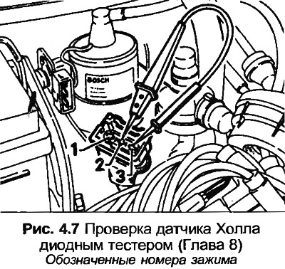
23. Connect the diode tester between terminals 2 and 3 on the connector.
24. Turn the engine with the starter, the LED should light, indicating that the Hall sensor is functioning correctly.
25. If the LED does not light, connect a voltmeter (preferably digital) between the two outer terminals on the connector. Turn on the ignition, the voltmeter should show at least 9 volts.
26. Reconnect the connector, then pull back the rubber boot to expose the clip.
27. Connect the diode tester between the center clamp connector and the positive battery terminal.
28. Crank the engine with the starter, the LED should light, indicating that the Hall sensor is functioning correctly. If the LED does not light, then either the Hall sensor or the FEI control unit is faulty.
Power output block
29. First check that the ignition coil is in good condition, referring to Chapter 6.
30. Compress the spring clip, disconnect the wiring connector from the power output block on the ignition coil.
31. Turn on the ignition, connect the voltmeter (preferably digital) between the two outer terminals on the connector. If battery voltage is not registered, check the wiring.
32. Connect the diode tester between terminals 2 and 3 on the connector.
33. Crank the engine with the starter, the LED should light, indicating that the Hall sensor is functioning correctly. If not, check the Hall sensor.
34. Turn off the ignition and reconnect the connector.
35. Disconnect the wiring from the Hall sensor on the distributor.
36. Connect the voltmeter (preferably digital) between terminals 1(-) and 15(+) on the ignition coil, then turn on the ignition.
37. On the PS engine, the voltage should initially be 2 volts, then drop to zero within 1-2 seconds.
38. Connect the center terminal of the Hall sensor wiring to ground. The voltage should briefly increase to 2 volts, then decrease to zero within 1-2 seconds.
39. If not, replace the power output unit or control unit. Also check if the ignition coil is leaking sealant. If yes, replace the ignition coil.
FEI Control Unit Multi-Pin Plug
40. The following tests require the use of a digital multimeter, which must be set to the correct measurement range before connecting to the terminals, otherwise electrical components may be damaged.
41. Make sure the battery is in good condition. Turn off the ignition.
42. Remove the trim from the right driver's side.
43. Remove the screws and lower the block.
44. Disconnect the multi-plug and, if necessary, the vacuum hose.
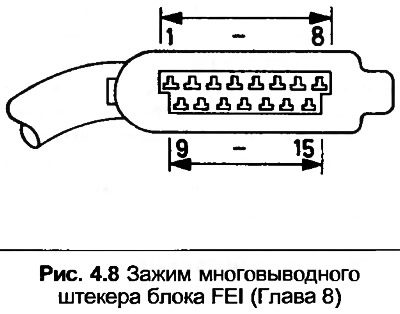
45. Using Fig. 4.8, connect the voltmeter between terminals 3 and 5. The device should show the battery voltage.
46. Connect a voltmeter between terminals 3 and 6. With the ignition on and the throttle closed, the meter should show battery voltage.
47. Connect a voltmeter between terminals 3 and 8. With the ignition on and the throttle fully open, the meter should indicate battery voltage.
48. Connect the voltmeter between terminals 3 and 10. With the ignition on, the device should show the battery voltage.
49. Connect a voltmeter between terminals 4 and 5. With the ignition on and the fuel pump relay contacts connected, the meter should show battery voltage.
50. Switch the meter to resistance measurement mode. Disconnect the multi-pin plug from the KE-Jetronic control unit, then connect the ohmmeter between terminal 2 on the FEI control unit and terminal 25 on the KE-Jetronic control unit. The meter should read 0 ohms.
51. Disconnect the multi-pin plug of the power output unit, short-circuit terminals 2 and 3. Connect the ohmmeter between terminals 3 and 12. The device should show 0 Ohm.
52. Disconnect the knock sensor wire contact and short all three clamps. Connect an ohmmeter between clamps 13 and 14. The device should show 0 Ohms.
53. Disconnect the wire contact from the Hall sensor and short the outer clamps. Connect the ohmmeter between clamps 7 and 15. The device should show 0 Ohm.
54. Short the center and brown-white wires on the Hall sensor. Connect an ohmmeter between terminals 7 and 9. The device should show 0 Ohms.
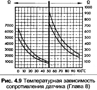
55. Check that the wiring is connected to the temperature sensor. Connect an ohmmeter between terminals 3 and 1. The resistance should be within the tolerances shown in Fig. 4.9 according to the temperature.
The original article is posted on the resource: audimanual.ru