
Repair Chevrolet Repair Toyota Repair Honda Repair AvtoVAZ Repair Mercedes-Benz Repair BMW Repair Opel
Home  |  Contacts  |  Sitemap  |    
English Русский
Български
Беларускі
Український
Српски
Hrvatski
Română
Polski
Slovenský
Magyar
AudiManual.ru


  • AUDI 80
  • AUDI 100
  • AUDI A3
  • AUDI A4
  • AUDI A6
  • AUDI A8
  • AUDI Q
  • OTHER
  • ARTICLES
B4 (1991-1996) B3 (1986-1991) B3 (1986-1991, petrol) B2 (1979-1986)

Distributor — disassembly, inspection and assembly (Audi 80 B3)

  • Home
  • Audi 80
  • B3 (1986-1991, petrol)
  • Power unit
  • Ignition system
  • Distributor — disassembly, inspection and assembly
            0
Warning: The distributor rotor on some 20 valve engines is fixed to the shaft and if damaged the complete distributor will need to be replaced. Do not attempt to remove the distributor rotors on these engines.
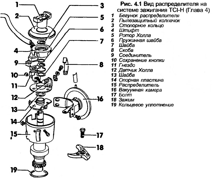

Warning: The distributor rotor on some 20 valve engines is fixed to the shaft and if damaged the…


1. Wipe the outside surface of the distributor.

2. Remove the distributor rotor from the drive shaft, then lift the dust cap. Make sure that the cover retaining bracket does not contaminate the Hall rotor.

3. Mark the position of the Hall rotor relative to the drive shaft, then remove the retaining ring, take out the rotor together with the mounting pin.

4. Remove the flat and spring washers, noting their installation positions.

5. Where is it used?; remove the screws, take out the vacuum chamber.

6. Remove the retaining ring and washer from the backing plate and remove the screws securing the socket to the distributor side. Remove the magnetic pickup and socket.

7. Remove the side screws, lift the support plate and thrust washer. Also remove the spring clips.

8. Clean all parts and check their condition.

9. Inspect the inside of the distributor cover for signs of burning or wear. Make sure the carbon brush in the center of the cover is in good condition and moves freely against the spring tension.


10. Check that the distributor rotor is not damaged. Use an ohmmeter to measure the resistance between the copper contact in the center of the distributor rotor and the copper contact at the edge of the rotor. The resistance should be 600-1400 ohms.

11. Where fitted, apply vacuum to the pipe connection to the vacuum diaphragm and check that the diaphragm block return rod moves. Secure the diaphragm with vacuum and check that it is not leaking.

12. Assemble the distributor in the reverse order of disassembly, lubricate the working surface of the bearing plate. Finally, quickly rotate the drive shaft and check that the Hall rotor is not jammed or bent.

The original article is located on the online resource audimanual.ru
The article was checked by auto expert Timur Bazhenov
This article is available at russian, bulgarian, belarusian, ukrainian, serbian, croatian, romanian, polish, slovak, hungarian

Share information:
Previous articles
Audi 80 B3: Ignition system
Next articles

Distributor — removal and installation
General description of the ignition system
Ignition System Specifications
Transistor Coil Ignition (TCI-H) — Description
Transistor Coil Ignition (TCI-H) Testing
Fully Contactless Ignition (FEI) — Description
Fully Contactless Ignition (FEI) — Test


Similar articles on other Audi car models:
Ignition distributor Audi 100 C4 (1990-1994, petrol)
Ignition distributor Audi A4 B5 (1994-2001, petrol)
Ignition distributor Audi A6 C4 (1994-1997)
Air duct and air distributor in the cabin Audi Q5 Type 8R (2008-2017)
Link to this page in different formats


Visitor comments

No comments yet


How much will 50 + 36 =


80(B4, 1991-1996) 
  • General information
  • User manual
  • Maintenance
  • Troubleshooting
  • Power unit
  • Engine
  • Cooling system
  • Heating and ventilation
  • Petrol injection
  • Diesel fuel system
  • Fuel system
  • Exhaust systems
  • Ignition system
  • Transmission
  • Clutch
  • Car gearbox
  • Chassis
  • Brake system
  • Suspension and steering wheel
  • Body
  • Body and trim
  • Electrical equipment
  • Electrical system
  • Electrical circuits
 
80(B3, 1986-1991) 
  • General information
  • Repair characteristics
  • Maintenance
  • Power unit
  • Gasoline engine
  • Diesel engine
  • Engine lubrication system
  • Fuel system (gasoline)
  • Injection system (gasoline)
  • Fuel system (diesel)
  • Ignition system
  • Cooling system
  • Heater
  • Exhaust system
  • Transmission
  • Clutch and gearbox
  • Chassis
  • Steering
  • Brake system
  • Car suspension
  • Body
  • Body elements
  • Electrical equipment
  • Power devices
  • Lighting and appliances
  • Electrical circuits
 
80(B3, 1986-1991, petrol) 
  • General information
  • User manual
  • Maintenance
  • Power unit
  • Engine 4-cylinder
  • Engine 5-cylinder
  • Cooling system
  • Fuel and exhaust systems
  • Ignition system
  • Transmission
  • Clutch
  • Mechanical transmission
  • Automatic transmission
  • Drive shafts
  • Chassis
  • Brake system
  • Suspension
  • Steering
  • Body
  • Exterior
  • Interior
  • Electrical equipment
  • Equipment and devices
  • Electrical circuits
 
80(B2, 1979-1986) 
  • General information
  • User manual
  • Power unit
  • Engine FZ
  • Engine EP, YP, YZ, DT, DS, DZ
  • Transmission
  • Clutch
  • 4 speed gearbox
  • 5 speed gearbox
  • Front wheel drive
  • Chassis
  • Front suspension
  • Rear suspension
  • Steering
  • Brake system
  • Electrical equipment
  • Equipment and devices
  • Electrical circuits
 
AudiManual.ru © 2017-2026 · Mobile version · Feedback · Sitemap: EN BG BY UA RS HR RO PL SK HU · Site search · News and articles
80 B2 · 80 B3 petrol · 80 B3 · 80 B4 · 100 C3 diesel · 100 C3 petrol · 100 C3 · 100 C4 petrol · 100 C4 · A3 Type 8L · A4 B5 petrol · A4 B5 · A4 B6 petrol · A4 B6 · A4 B7 · A4 B8 · A6 C4 · A6 C5 · A6 C5 Allroad · A8 D2 · Q5 Type 8R · Q7 Typ 4L · Audi A2 ·
This site uses cookies 🍪. Click the button to accept this fact.