
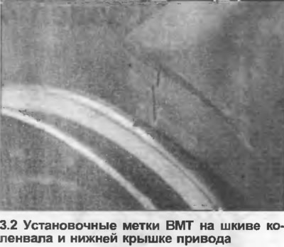
2. Continue turning the engine clockwise until the TDC marks on the crankshaft pulley and the lower drive cover are aligned (photo). On a 20-valve (7A) engine, you will need to align the "0" mark on the flywheel with the corresponding mark in the transmission case bore, as there is no mark on the pulley. This procedure can be used for all other engines.
3. For additional control, the top cover of the drive can be removed. The TDC mark on the camshaft sprocket should be aligned with the pointer on a 20-valve engine, or the top edge of the cylinder head on other engines (see Section 1).
4. Mark the exact alignment of the distributor housing and the engine block or cylinder head relative to each other.
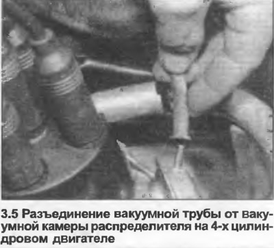
5. Disconnect the vacuum pipe from the vacuum chamber (photo).
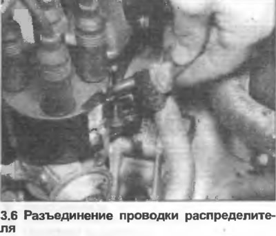
6. Compress the spring clip, disconnect the wire contact (photo).
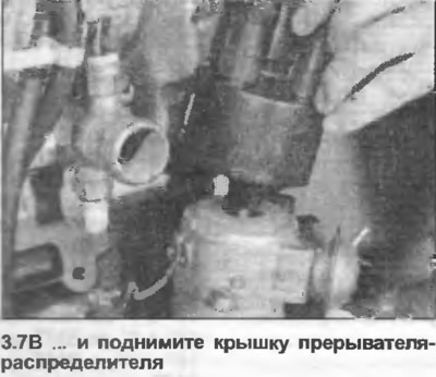
7. Remove the screen (if any), then remove the brackets and lift the cover off the distributor (photo).

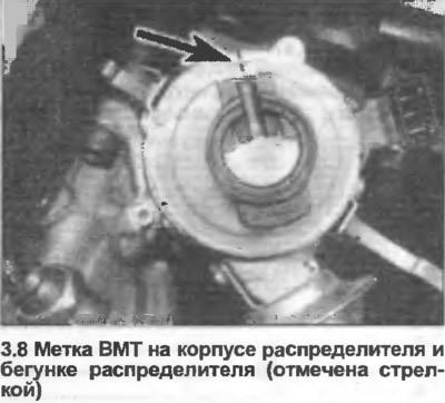
8. Check if there is a mark on the upper frame of the distributor housing that coincides with the center of the distributor rotor. If not, make a mark with a pencil (photo). On a 20-valve engine, a special Audi tool, shown in Fig. 4.21, is used to align the distributor rotor. If necessary, a similar tool can be made from an old distributor breaker cover.
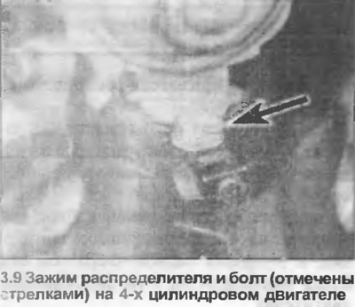
9. Unscrew the clamp bolt or nut, remove the clamp (photo). The bolt may have a plug installed.
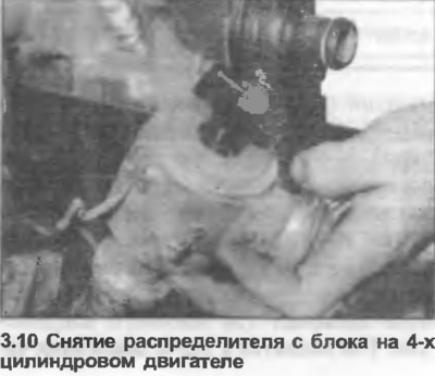
10. Remove the distributor from the block or cylinder head (photo).
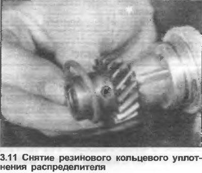
11. Check the condition of the rubber O-ring seal on the base of the distributor, if necessary, remove and replace it (photo). If present, also replace the gasket.
12. Check that the crankshaft remains in the TDC position.
13. Turn the distributor runner slightly from the TDC position clockwise, then position the distributor in the hole in the block or head, aligning the previously made marks on the housing and block or head.
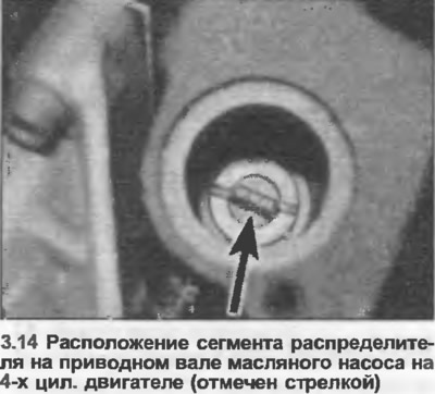
14. Lower the distributor back into place, check that the distributor rotor has moved counterclockwise to its original position. On a 4-cylinder engine, if the distributor does not fit completely, remove the block and use a screwdriver to turn the oil pump drive shaft slightly, then try again (photo).
15. Check that the pre-made marks are aligned, then install the clamp and tighten the bolt or nut.
16. Install the distributor cover, wiring, and vacuum pipe. If removed, also install the drive cover.
17. Check and, if necessary, adjust the ignition timing as described in Chapters 13, 14 or 15.
[The article is a reprint of material from: AUDIMANUAL]