
Note: Audi recommends using the VAG 1315A digital multimeter or VAG 1526 multimeter for the most accurate data during the following tests, as the internal resistance of some ohmmeters may affect the results obtained.
Ignition coil
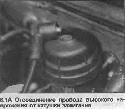
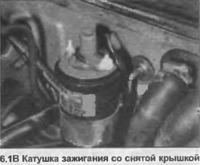
1. Disconnect the wiring and cover from the ignition coil (photo). Mark the location of each wire if necessary.
2. Connect the device between terminals 1(-) and 15(+), the resistance of the primary winding should correspond to the data in the Specifications.
3. Connect the device between terminals 4 (HT) and 15(+), the resistance of the rotor windings must correspond to the data in the Specifications.
4. Connect the electrical wiring.
Switch block
5. Check the ignition coil as described in points 1-4.
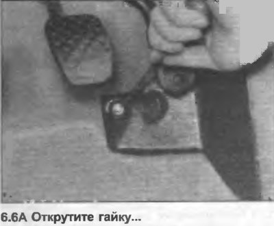
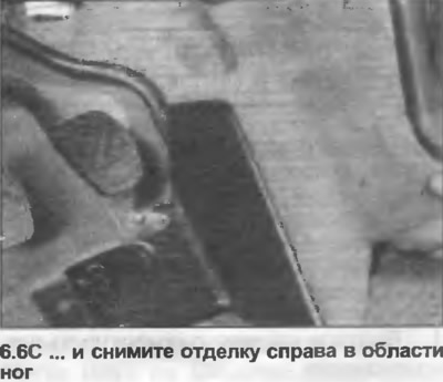
6. From inside the vehicle, remove the trim in the left or right footwell (according to the model) (photo).

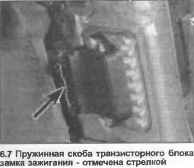
7. Press the spring clip together and pull out the connector (photo).
8. Connect the voltmeter between terminals 2 and 4 (Fig. 4.3).
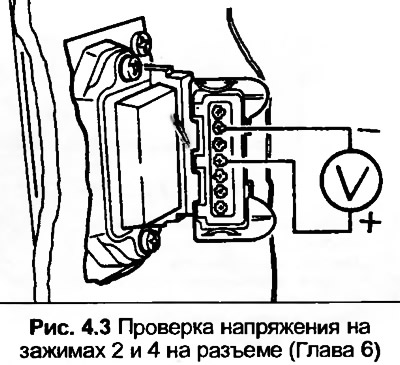
9. Turn on the ignition and check that the voltmeter registers battery voltage. If not, check the wiring.
10. Turn off the ignition, then disconnect the voltmeter and reconnect the connector.
11. Squeeze the spring clip together and disconnect the wiring from the distributor.
12. Connect the voltmeter to terminals 1(-) and 15(+) on the ignition coil.
13. Turn on the ignition, the voltage should be about 2 volts at first, then drop to zero within one or two seconds. If not, replace the switch unit. Also check if the sealant has leaked from the ignition coil. Replace the ignition coil if necessary.
14. Connect the center clamp of the distributor wire contact to ground. The voltage should briefly increase to 2 volts. If not, check the center wire of the clamp or replace the switch.
15. Turn off the ignition.
16. Connect the voltmeter to the outer terminals of the distributor wire contact.
17. Turn on the ignition, the voltmeter should show at least 5 volts.
18. Disconnect the voltmeter and reconnect the wire contact to the distributor.
19. If damage is still not found, check the wiring between the distributor and the switch unit and if the wiring is not damaged, replace the switch.
20. Disconnect the voltmeter and connect the connector. Install the trim on the left or right side of the footwell.
Distributor Hall Sensor
21. Before checking the Hall sensor, check the switch assembly and ignition coil as described earlier and make sure the related wiring is in good condition.
22. Disconnect the high voltage wire from the breaker-distributor cover and connect it to a suitable ground point using a wire of suitable length.
23. From inside the vehicle, remove the trim on the left or right side of the footwell.
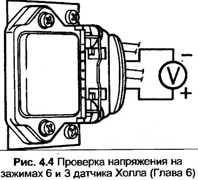
24. Connect the voltmeter between terminals 3 and 6 on the switch block, leaving the connector connected to the switch.
25. Turn on the ignition.
26. Using a wrench on the crankshaft pulley bolt, slowly turn the engine clockwise while watching the voltmeter readings. The voltage should alternate between zero and 2 volts. If not, replace the Hall sensor.
27. Turn off the ignition, disconnect the voltmeter, install the trim and connect the high-voltage wires.
[The original text of the material can be found on the website AudiManual.ru]