
Table of contents: Self-control system ↓ Ignition coil ↓ Control unit ↓ Hall sensor ↓ Power output block ↓ Permanent Damage Memory - Reset ↓
Warning: Before disconnecting any electrical wiring (including high voltage) from the ignition system, the ignition must be switched off. Failure to observe this precaution may result in damage to the integrated circuit components and electric shock.
Self-control system
1. The control unit is equipped with a fault memory that functions when the ignition is on. Fault information is stored in a permanent memory that must be cleared after the fault has been corrected. Other faults are stored in an additional memory that is not reset when the ignition is turned off, but is automatically updated when the engine is started.
2. The following points describe the method of reading damage data using a diode tester. Audi dealers use a special electronic damage reader, but this is not usually available to the home mechanic.
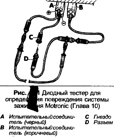
3. Prepare the diode tester and wiring, make a test circuit as shown in Fig. 4.11.
4. Check the serviceability of fuses 13, 21, 27 and 28. Turn off the air conditioner and check the reliability of the cylinder head earth cable fastening.
5. Start the engine and drive the car for at least five minutes. During this time, the engine speed should exceed 3000 rpm, to do this, briefly press the accelerator pedal fully several times.
6. Start the engine at idle speed. Do not increase the engine speed during the following tests. The engine must be warmed up to normal operating temperature.
7. If the engine does not start from the starter within six seconds, leave the ignition on.
8. Locate the two test connectors on the front driver's side footwell area and connect the wiring as shown.
9. Connect the connector and sockets C and D together for at least four seconds.
10. Disconnect the connector and socket, then count the number of flashes of the diode tester. The sequence begins with a signal that glows for 2.5 seconds and a pause lasting 2.5 seconds, then pulses are given after 0.5 seconds. Count the number of each group of signals. The result will be a four-digit number. If no damage is found, the code 4444 will be given (four groups of four flashes).
11. Check for further damage by repeating the procedure in step 9.
12. Further testing of the KE-Motronic system is described in Section 3.
13. The decoding of damage codes for the ZA engine is given in the following table.
- 1111 Control unit
- 2113 Engine speed signal, air flow meter plate is stuck, Hall sensor is faulty
- 2121 Idle speed switch I throttle valve
- 2123 Switch II fully open throttle
- 2141 Knock Control at Limit
- 2142 Knock Sensor
- 2231 Idle Speed Stabilization Override Setting Limits
- 2232 Air flow meter potentiometer
- 2312 Coolant Temperature Sensor
- 2341 Lambda control at the limit
- 2342 Lambda control
- 2343 Fuel mixture control unit limit, lean
- 2344 Fuel mixture control unit limit, rich
- 4431 Idle speed control valve
- 4444 No damage
- 0000 End of damage indication
14. Testing of individual components is given in the following paragraphs. Before removing any component, check the associated wiring. Note that incorrect ignition timing can cause the knock sensor to reach the control limit and cause the corresponding fault indication. After reading the fault from the permanent memory, the memory must be cleared as described in paragraphs 28-32. The main memory will be cleared when the engine is started.
Ignition coil
15. Be guided Chapter 6, paragraphs 1-4.
Control unit
16. If the self-test procedure shows damage to the control unit, it must be replaced.
Hall sensor
17. Be guided Chapter 8, paragraphs 21-28.
Power output block
18. First check the ignition coil for proper operation as described in Chapter 6.
19. Squeeze the spring clip together and disconnect the wire contact from the power output block connector behind the ignition coil.
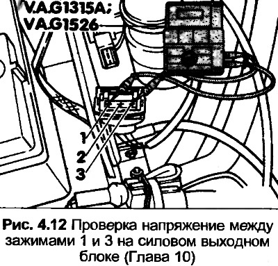
20. Turn on the ignition, then connect the digital multimeter (switch to voltage measurement mode) between the two outer terminals (1 and 3) on the connector. If the meter does not show battery voltage, check the wiring.
21. Connect the diode tester between terminals 2 and 3 on the connector.
22. Quickly rotate the engine with the starter, check the LED glow. If the diode does not light, check the Hall sensor.
23. Turn off the ignition, reconnect the connector.
24. Disconnect the wire contact from the Hall sensor on the distributor.
25. Connect a digital multimeter between terminals 1(-) and 15(+) on the ignition coil, then turn the ignition on.
26. Using a piece of wire, connect the center clamp of the Hall sensor wire contact to ground. The voltage should first increase to 2 volts, then drop to zero within 1-2 seconds.
27. If the voltage does not drop, install a new power output module or control module, and also check for leakage of sealant from the ignition coil. If necessary, replace the ignition coil.
Permanent Damage Memory - Reset
28. Connect the special test cable as shown in Fig. 4.11. The ignition must be off.
29. Connect the connector and socket C and D.
30. Turn on the ignition, the LED should light up.
31. Disconnect the connector and socket C and D for at least four seconds, the code - 0000 should appear.
32. Reconnect the connector and socket within five seconds, then disconnect them, the LED should be continuously on.