
General check of the ignition system
Special tools are needed for systematic troubleshooting. These devices are usually available at service stations. Therefore, only basic checks are described here:
1. Check the voltage and state of charge of the battery, while referring to the subsection Battery check.
2. Check all fuses.
3. Disconnect and reconnect all plug connections related to the electronic engine management system. Check the position of the plug connections and the fixation of the cables in the engine compartment.
4. Check up reliability of connections with weight.
5. Check tightness of hoses and pipelines. Pay attention to damage to the hoses. Secure loose connections.
6. Check all high voltage wires for a secure fit. Damaged insulation can cause a spark to ground.
7. There may be high voltage leaks on the inside of the distributor cap on a 1.6L engine. They can be identified by thin black lines between the contacts.
8. To check if the ignition system is receiving voltage or current, follow the guidelines below, but note that the presence of current does not necessarily mean that there is sufficient voltage.
Checking the current supply
A voltmeter is needed to check:
Bo first, check the appropriate fuse (№32).
Engines 1.6 l
9. Remove the plug from the ignition output stage next to the ignition coil.
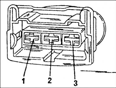
10. Connect a voltmeter between pin 1 positive and pin 3 (weight).
11. Turn the ignition on and check that the voltmeter shows a voltage close to the battery voltage. If not, then check the wire all the way to the switch (castle) ignition.
1.8L engine without turbocharger
12. Remove the cover in the middle of the motor and disconnect the plug from the output (terminal) cascade.
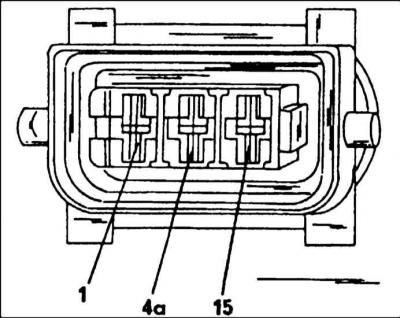
13. Connect a voltmeter to the middle terminal 4a and to "mass". Turn on the ignition. The voltage should roughly match the battery voltage. If not, check the wire all the way to the ignition switch.
1.8L engine with turbocharger
14. Do the same with the difference that a voltmeter must be connected between the black (blue) wires and brown (yellow) wires. The measurement results should be the same as for a conventional engine without a turbocharger.
Coil test (coils) ignition
Different motors require different operations.
Engine 1.6 l
15. The first step is to check the appearance of the ignition coil. A burnt-out coil can sometimes have a molten mass come out to fill the coil.
16. To measure, you need an ohmmeter with the ability to measure high resistances.
17. Switch off the ignition and disconnect the wire from the connection.
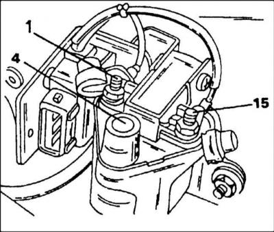
18. Measure the resistance between terminals 1 and 15 with an ohmmeter. The resistance of the primary winding is measured, which should be 0.5–1.5 ohms.
19. Connect an ohmmeter between terminals 15 and 4. The secondary winding resistance to be measured should be 5-9 kΩ.
20. If the indicated resistance values do not correspond to those measured, the ignition coil must be replaced. You can also check the ignition coil in the workshop.
1.8L engine without turbocharger
With this engine, the ignition coils and the output stage are connected to each other. Only a rough check is possible under the assumption that voltage is applied (engine cover removed):
21. Disconnect all plugs from injectors.
22. Disconnect the plug from the output stage and connect a test lamp to one of the outer contacts and to "weight". Turn the engine over with the starter and check that the lamp flashes.
23. Do the same test on the other contact. The lamp should flash again.
24. If no blinking is observed, then the malfunction may be in the following details:
- Wire connections;
- Control block;
- Sensors.
25. For replacement, you need to check the system in the workshop to establish the exact cause.
1.8L engine with turbocharger
On this engine, check the ignition coils again (the output stage is checked separately).
26. Disconnect all plugs from injectors. If, when checking the current and voltage supply, it is found that one candle does not work, then the ignition coils must be swapped. If there is no spark on the other spark plug, then the coil is faulty. To be completely sure of this, you need to connect the spark plug to another coil, since the spark plug can also be damaged.
27. If still no result, disconnect the plug of the corresponding cylinder and measure the voltage between the contacts. To do this, connect a voltmeter between both outer contacts of the plug and switch on the ignition. The voltmeter should show battery voltage. If this is not the case, then there is an open circuit in the power supply to the plug.
28. Connect control (verification) lamp to pins 2 and 3 of the plug and turn on the ignition and starter. If the lamp does not flash, you need to check the entire system in the workshop.
Checking the ignition switch
For 1.8l engines without a turbocharger, the commutator has already been checked along with the ignition coils. Other engines are checked separately.
Engine 1.6 l
The switch is located next to the ignition coil. To check, do the following:
29. Remove the plug from the output stage and connect a voltmeter between terminals 2 and 3
30. Turn the engine over with the starter and check that the voltmeter shows at least 2 V.
31. If this is not the case, it is necessary to replace the ignition coil and output stage together, having previously checked them in the workshop.
1.8L engine with turbocharger
The ignition switch is connected with two plugs, which are checked in different ways. One plug has 5 pins, the other has 4 pins. They are installed on the left and right side of the switch.
32. Disconnect plugs from all injectors.
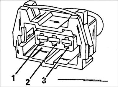
33. Disconnect the 4-pin plug from the output stage (under the air filter housing cover). The plug contacts are arranged in order from left to right. Connect one wire of the LED probe to "weight".
34. Connect the other wire of the probe in series to pins 1, 2, 3 and 4 of the plug, including the starter. During all checks, the LED should flash. If this is not the case, then there are faults. Plug the plug into place.
35. Remove the 5-pin plug. The plug contacts are arranged in order from left to right.
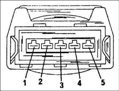
36. Connect the free wire of the LED probe in series to pins 1, 2, 4 and 5, including the starter (pin 3 in the plug plays a role "masses"). The LED should flash during these four checks. This means that the input signal goes to the switch.
37. If the described check gave a negative result, then you need to replace the switch.
Hall sensor test
As already mentioned, the Hall sensor for 1.8 liter engines is located on the front side of the cylinder head, directly above the toothed belt. During normal operation, the electronic engine control system determines the ignition timing for the first cylinder from the signal from the Hall sensor. If the signal is not received, then the cylinders cannot work for a long time with knock control. In this case, the knock control system does not work, the ignition timing is slightly delayed to prevent knocking. To check the Hall sensor, you need to proceed as follows:
38. Disconnect the injector plugs.
39. After removing the protective cover of the toothed belt, you can see the Hall sensor. The plug is at the bottom. Pull the rubber grommet on the plug of the Hall effect sensor back (the plug remains connected to the sensor).
40. Connect the LED voltage probe to pins 1 and 2 on the back. For this purpose, the contacts are marked on the back of the plug with numbers. Turn on the starter for a few seconds. At every second revolution of the engine, the LED should flash briefly.
41. Remove the plug from the Hall sensor and turn on the ignition.
42. Connect a voltmeter between pins 1 and 3 of the plug. The voltage value should be 4.5–5.5 V.
43. Now connect a voltmeter between pins 2 and 3 of the plug. The voltage should be 4.3–5.2 V.
44. If the voltage values are as specified, but the LED is flashing, the Hall sensor must be replaced. If the values of the measured voltages do not correspond to those indicated, then there is a malfunction in the wire connections. Eliminate in the workshop.
Checking the engine speed sensor
The speed sensor is located above the flywheel ring gear. An ohmmeter is needed to check it.
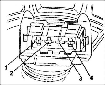
45. Disconnect the plug from the speed sensor (gray plug).
46. On the inside of the plug, connect an ohmmeter to pins 1 and 2 (No. 1 - on the left). The resistance value should be 480-1000 ohms. If the measured resistance is outside these limits, replace the sensor.
47. If the resistance is correct, connect an ohmmeter between pins 1 and 3 and between pins 2 and 3. The ohmmeter should indicate infinity, otherwise replace the sensor.
48. If all parts are working, then there may be a wire break.
Checking the knock sensor
The 1.6L engine has only one knock sensor. An electrical test of this sensor is not possible. Malfunctions can be determined by polling the memory of the diagnostic device using special devices. The plugs are behind the coolant expansion tank and can be checked for corrosion or other external damage. All other work is done in the workshop.
Visitor comments