
View of the 1.6L petrol engine compartment and a list of control system components (the illustration does not show everything)
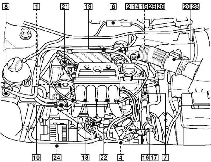
- 1 - Camshaft Position Sensor - CMP
- 2 - Closed Throttle Position Switch - CTP
- 3 - Clutch pedal switch - CPP
- 4 - Crankshaft Position Sensor - CKP/Engine Speed Sensor - RPM
- 5 - Data Line Connector - DLC - Center Console
- 6 - Engine Control Module - ECM
- 7 - Coolant temperature sensor - ECT
- 8 - Evaporative Emissions Canister Purge Valve - EVAP
- 9 - Fuel filter - outside the tank
- 10 - Fuel pressure regulator
- 11 - Fuel pump built into the tank
- 12 - Fuel Pump Relay - Front Panel Relay Box, Position 4
- 13 - Heated λ-probe - HO2S - pre-catalytic
- 14 - Idle Speed Control Activator - ISC
- 15 - Idle speed control actuator position sensor - ISC
- 16 - Ignition amplifier
- 17 - Ignition coil
- 18 - Injectors
- 19 - Intake air temperature sensor - IAT, up to 98 g.
- 20 - Intake air temperature sensor - IAT, after 98.
- 21 - Intake manifold air control solenoid
- 22 - Knock sensor
- 23 - Air mass meter - MAF
- 24 - Power steering pressure switch - PSP
- 25 - Throttle control unit
- 26 - Throttle Position Sensor - TP
- 27 - Vehicle Speed Sensor - VSS - on transmission
View of the 1.8L naturally aspirated petrol engine bay and list of control system components (the illustration does not show everything)
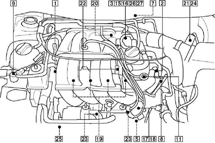
- 1 - Camshaft Position Sensor - CMP
- 2 - Camshaft position actuator
- 3 - Closed Throttle Position Switch - CTP
- 4 - Clutch pedal switch - CPP
- 5 - Crankshaft Position Sensor - CKP/Engine Speed Sensor - RPM
- 6 - Data Line Connector - DLC - Center Console
- 7 - Engine Control Module - ECM
- 8 - Coolant temperature sensor - ECT
- 9 - Evaporative Emissions Canister Purge Valve - EVAP
- 10 - Fuel filter - outside tank
- 11 - Fuel pressure regulator
- 12 - Fuel pump built into the tank
- 13 - Fuel Pump Relay - Front Panel Relay Box, Position 4
- 14 - Heated λ-probe - HO2S - pre-catalytic
- 15 - Idle Speed Control Activator - ISC
- 16 - Idle speed control actuator position sensor - ISC
- 17 - Ignition amplifier
- 18 - Ignition coil
- 19 - Injectors
- 20 - Intake air temperature sensor - IAT, up to 98 g.
- 21 - Intake air temperature sensor - IAT, after 98.
- 22 - Intake manifold air control solenoid
- 23 - Knock sensor
- 24 - Air mass meter - MAF
- 25 - Power steering pressure switch - PSP
- 26 - Throttle control unit
- 27 - Throttle Position Sensor - TP
- 28 - Vehicle Speed Sensor - VSS - on transmission
View of the 1.8L turbocharged petrol engine bay and control system list (the illustration does not show everything)
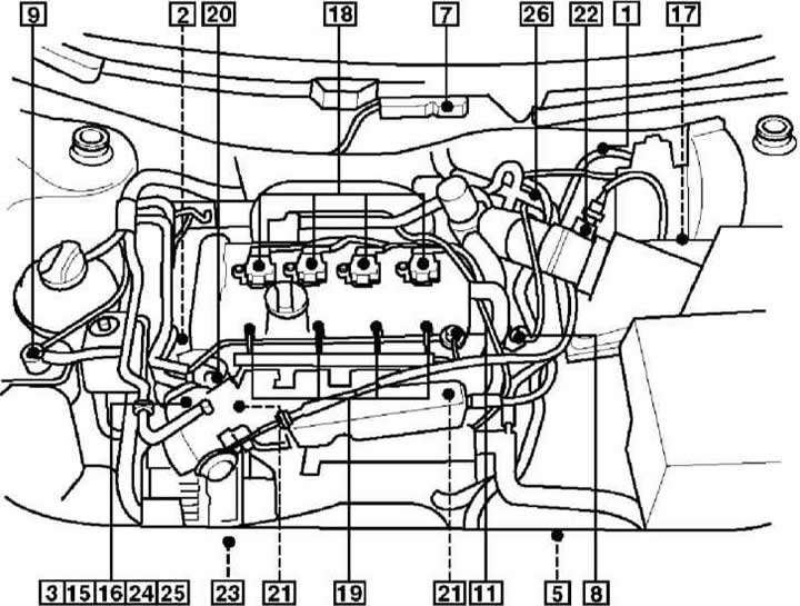
- 1 - Atmospheric pressure sensor - BARO
- 2 - Camshaft Position Sensor - CMP
- 3 - Closed Throttle Position Switch - CTP
- 4 - Clutch pedal switch - CPP
- 5 - Crankshaft Position Sensor - CKP/Engine Speed Sensor - RPM
- 6 - Data Line Connector - DLC - Center Console
- 7 - Engine Control Module - ECM
- 8 - Coolant temperature sensor - ECT
- 9 - Evaporative Emissions Canister Purge Valve - EVAP
- 10 - Fuel filter - outside tank
- 11 - Fuel pressure regulator
- 12 - Fuel pump built into the tank
- 13 - Fuel Pump Relay - Front Panel Relay Box, Position 4
- 14 - Heated λ-probe - HO2S - pre-catalytic
- 15 - Idle Speed Control Activator - ISC
- 16 - Idle speed control actuator position sensor - ISC
- 17 - Ignition amplifier
- 18 - Ignition coil
- 19 - Injectors
- 20 - Intake air temperature sensor - IAT
- 21 - Knock sensor
- 22 - Air mass meter - MAF
- 23 - Power steering pressure switch - PSP
- 24 - Throttle control unit
- 25 - Throttle Position Sensor - TP
- 26 - Turbocharger discharge control valve - TC
- 27 - Vehicle Speed Sensor - VSS - on transmission
View of the TDI diesel engine compartment and list of control system components (the illustration does not show everything)
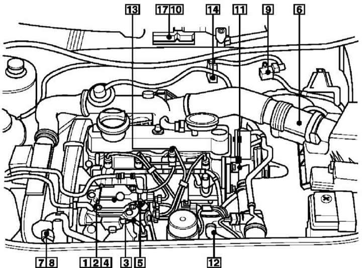
- 1 - Fuel temperature sensor
- 2 - Fuel lever position sensor
- 3 - Injector solenoid
- 4 - Fuel quantity adjustment solenoid
- 5 - Fuel cut-off solenoid valve
- 6 - Air mass meter
- 7 - Absolute pressure sensor in the pipeline
- 8 - Intake air temperature sensor
- 9 - Turbocharger pressure control solenoid
- 10 - Atmospheric pressure sensor - in the engine control unit
- 11 - Coolant temperature sensor
- 12 - Engine speed sensor
- 13 - Injector needle lift sensor
- 14 - Exhaust gas recirculation solenoid
- 15 - System Relay - #5 in Instrument Cluster Relay Panel
- 16 - Glow Plug Relay - in instrument cluster relay box, position 4
- 17 - Engine control unit
- 18 - Vehicle speed sensor
- 19 - Accelerator pedal position sensor - above the pedal
- 20 - Diagnostic connector - center console