
Table of contents: Reading fault codes ↓ Execution order ↓
The description of the elements of the electronic ignition and injection control system is given in the section Fuel and exhaust systems.
(If your vehicle is equipped with OBD II, there should be an entry on the nameplate under the hood "OBD II compliant" and there must be a 16-pin connector. As a rule, OBD II is equipped on models produced since 1996).
1. The OBD system includes several diagnostic devices that monitor individual parameters of the toxicity reduction systems and record detected failures in the on-board processor memory in the form of individual fault codes. The system also checks sensors and actuators, monitors vehicle maintenance cycles, and provides the ability to memorize even short-term failures during operation and clear the memory block.
Location of the diagnostic connector
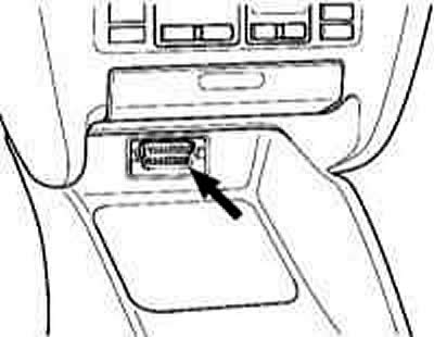
2. All models described in this Manual are equipped with a second-generation on-board diagnostics system (OBD–II). The main element of the system is the on-board processor, more often called the electronic control module (ECM) or the powertrain control module (PCM). The PCM is the brain of the engine management system. Initial data is sent to the module from various information sensors and other electronic components (switches, relays, etc.). Based on the analysis of data received from the information sensors, and in accordance with the basic parameters stored in the processor memory, the RCM generates commands to operate various control relays and actuators, thereby adjusting the engine operating parameters and ensuring maximum efficiency with minimum fuel consumption. Reading of the OBD-II processor memory data is performed using a special scanner connected to the 16-pin diagnostic connector for reading the database (DLC), located under the heater control panel.
Note: On some models, reading of fault codes stored in the self-diagnostic system memory can be performed using the "Check Engine" lamp.
3. Maintenance of engine management/exhaust gas reduction components is subject to special extended warranty obligations. You should not attempt to independently perform diagnostics of RSM failures or replace system components before the deadline for these obligations. Please contact the specialists of representative service stations.
Information about diagnostic devices
The use of a high-impedance digital multimeter in diagnostics of the systems under consideration significantly increases the accuracy of the measurements taken.
4. The proper functioning of injection system components and exhaust gas toxicity reduction is checked using a universal digital meter (multimeter). Using a digital meter is preferable for several reasons. Firstly, it is quite difficult to measure the value of an analog meter (sometimes it's impossible), determine the result of the reading with an accuracy of up to hundredths and thousandths, while when examining circuits that include electronic components, such accuracy becomes especially important. The second, no less important, reason is the fact that the internal circuit of the digital multimeter has a fairly high impedance (the internal resistance of the device is 10 mOhm). Since the voltmeter is connected to the circuit being tested in parallel, the accuracy of the measurement is higher, the smaller the current that passes through the device itself. This factor is not significant when measuring relatively high voltage values (9-12 V), but it becomes decisive when diagnosing elements that produce low-voltage signals, such as, for example, a λ-probe, where we are talking about measuring fractions of a volt.
Parallel monitoring of signal parameters, resistances and voltages in all control circuits is possible using a splitter connected in series to the engine control unit connector. In this case, with the engine off, running or while the car is moving, the signal parameters are measured at the splitter terminals, from which a conclusion is made about possible defects.
5. For diagnostics of electronic systems of the engine, automatic transmission, ABS, SRS, special diagnostic scanners (Pointer) or testers (Retriever) with a specific cartridge are used (if provided), universal cable and connector. In addition, for this purpose, you can use an expensive specialized automotive diagnostic computer, specially designed for full diagnostics of most systems of modern cars (for example, ADC2000 from Launch HiTech, or ESA560, FSA, BEA from Bosch), or a regular computer with a special cable and an OBD browser program (for example, the Bosch ESI[tronic] program in Russian (www.ESItronic.com, the Motor–tester, Mytester, VagCom and VagTool programs or those offered on the websites www.carsoftinternational.com or www.obd–2.com).
Universal K–L–line adapter, serves to match signals of the RS–232 port and ISO–9141 (K–line) and ALDL interfaces. Various cables required for diagnostics of a specific car brand can be connected to the adapter connectors. Switches and indicator elements installed in the adapter allow you to select the necessary operating modes and roughly evaluate the operation of the output lines. Thus, the glow of the green LED marked L–line indicates the connection of the L line to the car body. The glow of the red LED marked K–line indicates the high potential that is present at this moment on the K line. When the connection with the car is established, the blinking of the indicators may be imperceptible to the eye due to the high exchange rate. Connection to the computer is made directly to the 25-pin COM–port or using the "RS–232 Cable 25 pin – 9 pin" to the 9-pin COM–port.
Some scanners, in addition to the usual diagnostic operations, allow, when connected to a personal computer, to print out the basic diagrams of electrical equipment stored in the memory of the control unit (if pledged), program the anti-theft system, monitor signals in the car circuits in real time.
6. Reading the fault codes recorded in the memory of the self-diagnostic system, on some vehicles, can also be done using the "check engine" indicator on the dashboard.
7. For diagnostics, devices from ToolRama, Inc. (3500 NW Boca Raton Blvd., Boca Raton, Florida, 33431, USA 1 877 866 5726 – 561 750 4511 – 561 338 8447 FAX) can also be used:
- tester R000 or scanner P000 with cartridge T043 or T053,
- universal cable N000,
- black or white connector N003;
- multiplexer N002A;
- connector N004.
8. The scanner only reads the fault memory and clears the fault memory. In addition, the scanner only supports the ISO protocol. The tester can additionally activate and display current data and supports the SAE and ISO protocols.
All tester cartridges can be used in the scanner as well. In this case, the functions will be limited to reading and clearing memory only.
9. For most vehicles produced since 1996 that support the SAE/ISO 9141 OBD II protocol, an OBD II cartridge can be used that performs the following functions:
Read and clear OBD II trouble codes. Display oxygen sensor test results.
Continuous monitoring of ignition systems, injection systems and components.
Displays a list of current data and recorded intermittent failures:
- Absolute pressure in the intake manifold;
- Oxygen sensor voltage;
- Engine coolant temperature;
- Estimated engine load;
- Car speed;
- Fuel quality;
- Air flow (by mass);
- Ignition timing;
- Throttle position;
- Intake air temperature.
In addition to "P0" fault codes, the tool also displays "P1" enhanced codes for Acura, Audi, BMW, Chrysler, Dodge, FORD, Geo, GM, Honda, Hyundai, Infinity, Kia, Lexus, Lincoln, Mercury, Mazda, Mercedes, Mitsubishi, Nissan, Porsche, Saturn, Seat, Skoda, Subaru, Suzuki, Toyota, Volvo, VW.
10. Features of the specialized automotive diagnostic device ADC2000:
- Built-in 4-channel oscilloscope with standard preset for 19 sensors.
- Ignition system analyzer for checking primary and secondary circuits (with voltage up to 100 kV) on systems with a distributor or separate ignition coils - with control of combustion time, peak voltage value, ignition timing, current, and speed.
- Two-channel multimeter with digital and graphical representation of data on voltage (150 V), frequency (1100 kHz), current (150 A).
- Built-in scanner for the main systems on cars: VAG, MB, BMW, Volvo, Toyota/Lexus, Mitsubishi, Nissan, Honda, Mazda, GM, Ford, Chrysler, Daewoo, Hyundai, Kia, Samsung, as well as on cars supporting the OBD–II protocol.
- No cartridges are required - you can update the device's software yourself by downloading the necessary updates from the Internet.
- Software for communication with a personal computer.
11. Information on the use of these devices is contained in the accompanying documents.
12. To carry out diagnostics, we recommend that you seek qualified assistance from service station specialists.
ISO 9141–2 (Chrysler, European and most Asian models) Contacts 4, 5, 7, 15, 16
output No | Purpose |
4 | Connection to the body |
5 | Housing - signal output |
7 | K Line, ISO 9141 |
15 | L-Line, ISO 9141 |
16 | Plus battery via fuse. Under voltage, in any position of ignition switch |
Reading fault codes
Information content of the code bits of Type P 0 3 8 0 from left to right:
1st rank (left)
| P | power unit |
| B | body |
| WITH | chassis |
2 digit Source code
| 0 | standard SAE |
| 1 | extended - manufacturer-defined |
3rd rank System
| 0 | the system as a whole |
| 1 | air mixing (air/fuel induction) |
2 | fuel injection |
| 3 | ignition system or misfires |
| 4 | additional release control (auxillary emission control) |
| 5 | car speed and idle control. |
| 6 | input and output signals of the control unit |
| 7 | transmission |
4.5 ranks
Component or circuit fault sequence number (00–99)
Execution order
1. When a fault is detected that is repeated on two consecutive trips, the PCM issues a command to turn on the instrument cluster mounted "Check Engine" warning lamp, also called the malfunction indicator. The lamp will remain lit until the self-diagnostic system memory is cleared of the codes of detected faults stored in it (refer to Specifications). If the lamp flashes, a malfunction has been registered that can damage the catalytic converter. Reduce speed until the lamp goes out or remains on continuously. Reading fault codes in the OBD-II system can be done in various ways. The main method is reading using the devices described above, connected to the 16-pin DLC connector of the OBD-II system. Other methods are not available on all models. On some models, the flashing code (manufacturer-defined and different from SAE standard codes) can be read by a digital voltmeter or LED. It is possible to read the code from the "Check Engine" lamp.
2. Without starting the engine, turn on the ignition – the "Check Engine" indicator lamp should light, otherwise it should be replaced. After checking the lamp for proper condition, turn off the ignition again.
If the system memory is clear, the indicator lamp will not come on.
Starting the engine automatically interrupts access to the diagnostic system.
Clearing OBD-II memory
3. When a fault code is entered into the PCM memory, the "Check Engine" indicator light on the vehicle's instrument panel lights up. The code remains recorded in the module's memory.
4. To clear the ECM memory, connect a scanner to the system and select the CLEARING COEDS function in its menu (Removing codes). Then follow the instructions displayed on the instrument, or immediately remove the EFI fuse from its socket in the fuse box for 30 seconds. Alternatively, the system memory can be cleared by removing the fuse link (main fuse of the on-board electrical system), (you can also simply disconnect the positive cable from the battery).
It is not advisable to clear the OBD memory by disconnecting the negative battery cable, as this will erase the engine settings and cause the engine speed to become unstable for a short time after the initial start.
If your car stereo system is equipped with a security code, make sure you have the correct combination to activate the audio system before disconnecting the battery!
Disconnecting the battery also deletes the receiver's favorite radio station settings. To avoid damaging the ECM, disconnect and connect it only with the ignition off!
5. Ensure that the system memory is cleared before installing new emission control components on the engine. If the fault memory is not cleared before starting the system after replacing a failed information sensor, the PCM will enter a new fault code. Clearing the memory allows the processor to reconfigure to the new parameters. However, some instability of the engine speed may occur during the first 50-20 minutes after the initial start of the engine.