
Table of contents: Instrument cluster ↓ Engine oil temperature gauge ↓ Tachometer ↓ Digital watch with date indication ↓ Radio clock ↓ Coolant temperature gauge ↓ Fuel gauge ↓ Speedometer and trip meters ↓ Voltmeter ↓ Setting button/control button ↓ Indication of maintenance intervals ↓
Instrument cluster
The instrument cluster serves as the driver's information center for the vehicle.
Engine oil temperature gauge
The device shows the temperature of the engine oil.
Until the oil has warmed up, do not try to use the engine's full power. If, as an exception, the instrument's pointer enters the upper zone of the scale, reduce the engine speed. After this, the pointer should return to the normal operating range.
If the needle remains in the high temperature range, stop, turn off the engine and check the oil level. If the level is normal and the oil pressure warning light does not flash after starting the engine, you can drive to the nearest Audi dealership without running at high engine speeds.
Tachometer
The tachometer shows the engine shaft rotation speed per minute.
At a speed of less than 1500 rpm, shift to the next lower gear. The beginning of the red sector of the scale corresponds for all gears to the range of maximum revolutions permissible for a short-term running-in and warmed-up engine. At the latest when the arrow reaches this sector of the scale, shift to a higher gear, set the control lever to position "D" or reduce the gas.
Caution! Only a short-term entry of the tachometer needle into the red sector of the scale is allowed - risk of engine damage! The beginning of the red scale depends on the engine version.
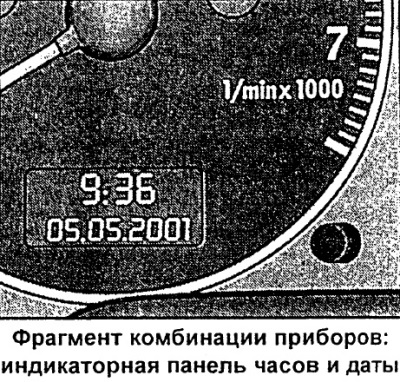
Digital watch with date indication
The car is equipped with a quartz clock or a radio clock.
Setting the clock
- Pull the button (the hour indicator is flashing) and rotate it left/right.
Setting the minutes
- Pull the button several times until the minute display starts flashing.
- Rotate the button left/right.
Setting the calendar date
- Pull the button several times until the day, month or year indication starts flashing.
- Rotate the button left / right.
Display (remove)/call calendar date
- Pull the button until the full calendar date display starts flashing.
- Rotate the button left/right.
When the indicator stops flashing after pressing the button, the installation process and time/date programming are complete.
By pressing/pulling the clock setting button/control button (depending on the instrument cluster variant) with the ignition off, you can turn on the indicator panel lighting for a few seconds.
Radio clock
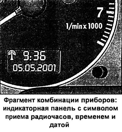
In the "radio-controlled quartz watch" mode, the radio information reception symbol appears on the indicator panel (radio tower with diverging waves). In this mode, manual change of the minute and date indication is not possible.
If you are with your vehicle in different time zones, you must manually change the clock display accordingly.
If there is no corresponding radio signal for three days, the watch automatically switches to the "quartz watch" mode. In this case, the radio information reception symbol indication disappears. If you need to re-set the time and calendar date, see the section "Digital watch with date indication".
Coolant temperature gauge
The coolant temperature gauge only works when the ignition is on. To avoid engine damage, please observe the following temperature instructions.
Cold Engine Temperature Range
If the needle is still on the left side of the scale, it means that the engine has not yet reached operating temperature. Avoid high revs, "full throttle" and significant engine load.
Operating temperature range
The engine has reached operating temperature if the temperature gauge needle fluctuates within the middle of the scale during normal driving. Under significant engine load and high outside temperatures, the needle may move further to the right on the scale. This should not be cause for alarm as long as the warning symbol does not flash on the instrument cluster display.
Signal symbol
Flashing of the signal symbol on the display indicates a drop in the coolant level or its overheating.
If the pointer moves significantly to the right of the scale, the coolant temperature is too high. Stop, switch off the engine and let it cool down. If the warning symbol lights up again after a short time while driving, contact an Audi dealer.
Warning! Never open the hood if you see or hear steam or coolant coming out of the engine compartment. Wait until the steam or coolant stops coming out.
Caution! Additional headlights and other add-on components that block the supply of cooling air impair the cooling effect of the coolant. At high outside temperatures and significant engine loads, there is a risk of engine overheating in this case!
One of the tasks of the front spoiler is to properly distribute cooling air while driving. If the spoiler is damaged, the cooling effect is reduced and there is a risk of engine overheating! Use qualified assistance.
Fuel gauge
The indicator only works when the ignition is on.
The fuel tank capacity is approximately 70 liters, and for a car with an eight-cylinder engine approximately 82 liters. If the arrow reaches the reserve field, the symbol lights up on the instrument cluster display). This means that there are approximately 9 liters of fuel left in reserve. The display of this symbol reminds you of the need to refuel.
Caution! Never run the fuel tank dry! Irregular fuel supply can cause misfires in the ignition system. As a result, unburned fuel will enter the exhaust system. This can lead to overheating and damage to the catalytic converter.
Speedometer and trip meters
The speedometer shows the speed and distance traveled.
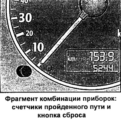
The distance traveled is displayed in kilometers (km). In some modifications, the indication is displayed in miles.
The lower counter records the total mileage of the vehicle in kilometers or miles.
Upper trip meter (daily nougat counter) records the distance traveled since the last reset. This allows you to measure specific sections of the distance traveled. The accuracy of the counter is 100 m or 1/10 mile. Reset (setting the value to zero) the upper counter is reset by pressing the reset button.
By pressing the clock setting/control button with the ignition off, the trip meter lighting can be switched on for a few seconds.
Malfunction indication
A fault in the instrument cluster is indicated by the display "dEF" in place of the trip odometer. Have the fault rectified by an Audi dealer as soon as possible.
Voltmeter
The voltmeter shows the electrical voltage of the on-board network.
The normal value is 1214 V. If the voltage drops below 12 V when the engine is running, check the power supply (battery and generator) at the Audi plant.
During engine starting, the voltage may drop below 8 V.
Setting button/control button
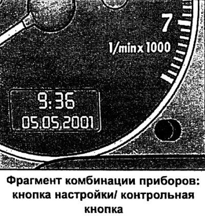
Functional purpose of the control button:
Turning on the digital clock and trip meter indication
By pressing the button with the ignition off, the digital clock display with date and trip meter indication is turned on for a few seconds.
Calling up the indication of the remaining number of kilometers before maintenance
By briefly pressing the button with the ignition on, the number of kilometers remaining before maintenance is displayed. The system operation can be checked with the engine off or running and at a speed of no more than 5 km/h.
Control of symbol indication
By pressing the control button twice with the ignition on, all symbols are sequentially called up to the malfunction monitoring system indication. The system operation can be checked both with the engine off and running and at a speed of no more than 5 km/h.
If there is a 1st priority level fault (red symbol) indication control is not possible.
Displaying instructions to the driver
When any symbol of the 1st priority level flashes on the display, you can briefly press the control button to turn on the lighting of the corresponding instruction to the driver again. For example:
MOTOR ABSTELLEN, OLSTAND PRUFEN (turn off the engine, check the oil level). The indicator goes out after approximately 5 seconds.
Speed alarm
By pressing the button while driving, the threshold value for warning level 1 of the speed alarm device can be programmed.
The warning level 2 threshold of the overspeed alarm device is only programmed when the ignition is switched off.
Indication of maintenance intervals
The maintenance interval indicator reminds you when the next maintenance is due.
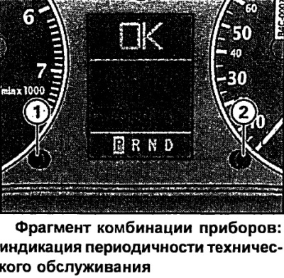
Indication of kilometers to maintenance
By briefly pressing button 1 with the ignition on, the number of kilometers until the next maintenance is displayed. The display can be displayed both with the engine off and running and at a speed of no more than 5 km/h. The display of the number of kilometers until maintenance is updated each time the ignition is turned on - the first time after 500 km after reset.
The display of a new car/car after maintenance will show the message SERVICE IN 15000 Km during the first 500 km of mileage.
This also applies to vehicles with "LongLife-Service".
Maintenance Reminder
When there are 2000 km left until the next maintenance, the following indication appears on the display when the ignition is turned on:
SERVICE IN 2000 km
After 5 seconds, the display switches to the normal display mode. The indication of the number of kilometers to maintenance is updated every time the ignition is turned on, until the time for maintenance.
The maintenance deadline has arrived
When the time comes for the next maintenance, the display shows "Service!" immediately after the ignition is turned on. After 5 seconds, the display switches to the normal display mode.
Returning the indication to its original position
The display is reset to its original position by the Audi service shop.
If the service was not carried out by Audi, the display is reset to its original position as follows:
- Turn off the ignition.
- With button 2 pressed, turn on the ignition. The display shows "SERVICE!".
- Press button 1 until the "SERVICE!" indicator goes out.
If the reset button is not pressed within 5 seconds, the display switches to normal display mode.
Note
- Return the indication to its original position only after maintenance. Otherwise, it will not correspond to reality.
- When the battery is disconnected, the service interval indication data is retained.
- If there is a 1st priority level fault (red symbol) it is not possible to display the number of kilometers left until maintenance.
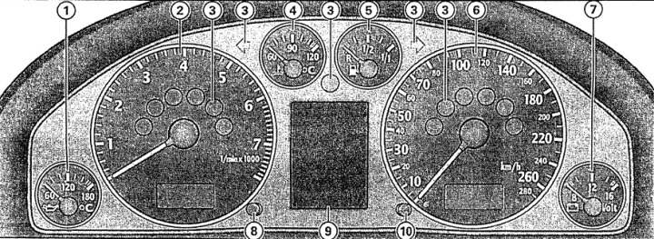
Instrument cluster
1 - engine oil temperature gauge
2 - tachometer with digital clock and date display
3 - control lamps
4 - coolant temperature indicator
5 - fuel reserve indicator
6 - speedometer with indicator panel of trip meters
7 - voltmeter
8 - clock setting button/control button
9 - display:
- indication of maintenance intervals;
- control lamps;
- outside temperature indication;
- 5-speed automatic transmission control lever position;
- position of the "multitronic" control lever;
- driver information system
10 - reset button
- daily trip meter;
- indication of maintenance intervals
Note: When the ignition is on, the instrument cluster needles are illuminated. When the light is on, the scales are additionally illuminated.