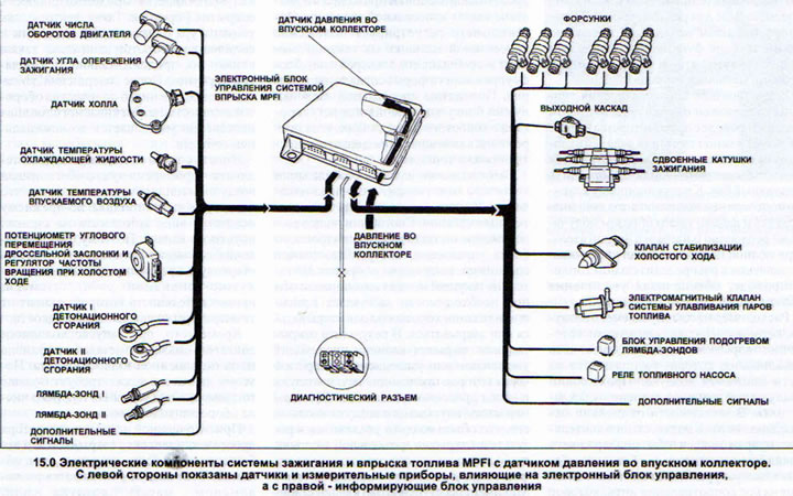
The AUDI 80 with a 2.8 - liter six-cylinder engine has a multi-point injection system MPI. The abbreviation MPI is derived from the first letters of the English name of this system Multi Point Injection. A distinctive feature of this system is the presence of an air mass flow meter installed in the air intake hose.
Cars with a 2.6-liter six-cylinder engine also have a multi-point injection system MPFI, which is identical to MPI. The main difference between the MPFI system and MPI is the method of measuring the volume or mass of the incoming air. The MPI system is equipped, as indicated, with an air mass meter, while MPFI has a pressure sensor in the intake manifold instead, which is installed in the electronic control unit and connected by a hose to the intake manifold. In addition, MPFI has an intake air temperature sensor in the intake manifold. The abbreviation MPFI is also made up of the first letters of the English name of this system Multi Point Fuel Injection.
The MPI/MPFI multi-point fuel injection system is quite voluminous. Its electronic unit is combined with the ignition system. The control unit has a self-diagnostic system. This means that all faults that occur during operation are recorded in the storage memory. Even short-term faults are recorded. As experience shows, they are the most difficult to detect defects. After every 50 engine starts, the fault record that occurred only once and was not repeated is automatically deleted.
The electronic control unit, based on the engine load and temperature, "allocates" the appropriate amount of fuel to it. For this purpose, the control unit varies the duration of the injector opening. The pressure in the fuel system is maintained at an approximately constant level and for this reason the amount of injected fuel can be regulated only by the duration of the injector opening. The control unit receives the corresponding information from a fairly large number of sensors or measuring devices.
- a) The air mass flow meter on vehicles with a 2.8L six-cylinder engine reports the amount of air received.
- b) The intake air temperature sensor, together with the intake manifold pressure sensor on vehicles with a 2.6L six-cylinder engine, also reports the amount of air received.
- c) The coolant temperature sensor provides information about the current engine temperature.
- d) The potentiometer at the throttle position provides data on the engine load.
- d) The engine speed sensor transmits information to the ignition and fuel injection systems.
- g) The ignition timing sensor reports the position of the crankshaft. In this way, the electronic control unit knows which cylinder should ignite the mixture and which one should inject fuel.
- c) Terminal 50 of the starter is the source of information about engine starting.
In addition, the control unit receives information from knock sensors, gearbox sensors and even from the air conditioner.
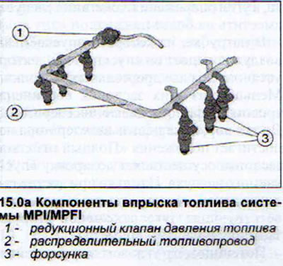
Each cylinder has one injector on the intake channel, which injects the amount of fuel required at the current moment, while simultaneously ensuring its finest atomization.
The injectors have electromagnetic control, which lifts the injector nozzle needle by approximately 0.1 mm, allowing fuel to exit. The injectors are triggered at the moment of the intake stroke and therefore the injected fuel does not have time to settle on the walls of the intake cable due to lack of time. This means that the system does not allow fuel losses.
The fuel distribution line is designed to supply fuel evenly to all six injectors. In addition, it functions as a fuel accumulator and prevents fuel pressure fluctuations.
The fuel pressure reducing valve is located on the right side of the fuel distribution line and is designed to maintain the fuel pressure at a constant level. This is achieved by diverting some of the fuel back to the fuel tank. A low-pressure air hose is connected to the pressure reducing valve, and the valve thus receives information about the engine load. At full load, the valve increases the pressure in the fuel distribution line, ensuring an increase in the volume of injected fuel.
The air mass flow meter, which is equipped with the MP1 multi-point fuel injection system, has a filament that is located in the air flow path. The passing air cools the filament to varying degrees. Depending on the degree of cooling, additional voltage is applied to the filament to maintain the filament heating constant. Such fluctuations in the heating temperature change the electrical resistance of the filament, which in turn is controlled by the electronic control unit.
As for the MPFI multi-point fuel injection system, it has a manifold pressure sensor. This sensor, located in the electronic control unit, is connected to the intake manifold by a thin hose. The manifold pressure is very important information for the control unit, based on which the engine load is recognized.
The intake air temperature sensor is screwed into the intake port of the third cylinder (back right). The information from this sensor, together with the information from the intake manifold pressure sensor, serves the electronic sensor to determine the engine load. At high intake air temperature (in this case the air density is low) there is a need to reduce the duration of fuel injection, and the ignition timing should be shifted to a later point.
In the branch pipe from which the inlet air enters the intake manifold, two throttle valves are installed. The smaller of these valves is connected by a "gas" cable to the accelerator pedal. Until the accelerator pedal reaches the "Full throttle" position, this valve doses the inlet air. And only when the accelerator pedal is sufficiently pressed does the corresponding rod open the second valve of a larger diameter.
The throttle angle potentiometer is driven by the throttle shaft. The potentiometer registers the current throttle position and reports it to the electronic control unit in the form of a voltage signal. The control unit needs the throttle position to regulate idle speed, select the ignition timing angle, and fuel injection duration.
The very name of the idle speed stabilization valve speaks of its purpose. The valve is only an executive body. It receives the corresponding order from the electronic control unit, which constantly compares the current engine speed with the nominal and, if necessary, forces the idle speed stabilization valve to open or close. As a result of opening or closing the valve, an increase or decrease in the opening through which air is admitted bypassing the throttle valve occurs. The air mass meter "believes" that the air volume has increased as a result of opening the throttle valve and provides a corresponding increase in the injected fuel. The MPI system has a continuously variable idle speed stabilization valve, MPFI - a valve with an executive electric motor.