
General description
In terms of the accuracy of the air-fuel mixture supply, the fuel injection system through one nozzle under the throttle valve is inferior to the injection system directly into the combustion chamber of the cylinder. This function is performed by the corresponding nozzle on each engine cylinder. For this reason, the four-cylinder engine with a power of 85 kW is equipped with a multi-point injection system. We are talking about an electronically controlled system with parameters stored in its memory, obtained during engine tests. These parameters concern the ignition timing, knock-free combustion of the air-fuel mixture, stabilization of idle speed and the forced idle mode.
This system is so powerful in terms of automation and computerization that the AUDI and VW engineers who created this system gave it the name Digifant, which is a word formation from parts of two words that can be translated from German as "software elephant" (see illustration 6.0).
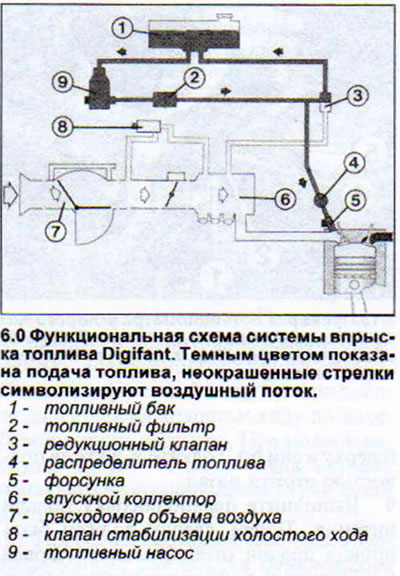
The Digifant electronic control unit receives information from the following sources via a multi-pin plug:
- a) data on the start and completion of engine starting are received from terminal 50 of the starter,
- b) the throttle position potentiometer informs the control unit of its current position,
- c) the Hall sensor on the ignition distributor informs about the engine speed,
- d) the lambda probe on the catalytic converter provides information on the oxygen content in the exhaust gases,
- d) the air flow meter potentiometer informs about the position of the valve shutter, which corresponds to the volume of incoming air,
- g) the temperature sensor on the air flow meter supplies data on the temperature of the incoming air,
- c) the coolant temperature sensor in the return pipe reports its temperature,
- e) The knock sensor on the cylinder block informs about knock combustion of fuel.
Based on the engine speed and load data, the electronic control unit determines the duration of the injector opening and, thus, the volume of fuel injected. For this purpose, its memory stores information about the engine's needs in all possible situations, obtained during testing, as well as parameters concerning the ignition advance angle. The electronic control unit can independently adjust the parameters set, but this is only possible after receiving so-called clarifying signals (for example, data on intake air temperature and coolant temperature).
There are two throttle valves on one pipe in the intake manifold. The smaller of these valves is connected by a gas cable to the accelerator pedal (see illustration 6.0a).
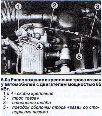
Until the accelerator pedal reaches the "Full throttle" position, this valve controls the intake air. Only when the accelerator pedal is pressed sufficiently does the corresponding rod open the second valve of a larger diameter.
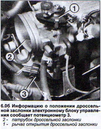
The throttle angle potentiometer recognizes its current position. Based on its information, idle stabilization, forced idle or maximum enrichment of the mixture is performed (see illustration 6.0b).
There is a pressure reducing valve in front of the fuel distributor, which regulates the pressure of the fuel supplied to the injectors. For this purpose, the valve is given a vacuum level in the intake manifold. When idling with the throttle valve closed and high vacuum, the valve reduces the fuel pressure. With a decrease in vacuum at the moment of increasing engine load, the pressure reducing valve increases the fuel pressure. The fuel pump creates a fairly high operating fuel pressure, but the pressure reducing valve can accordingly increase or decrease the fuel flow back to the fuel tank.
At each revolution of the crankshaft, the injectors inject fuel into the intake channel in front of the intake valve of the corresponding cylinder (see illustration 6.0b).
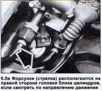
The injection duration is determined by the control unit. Thus, the corresponding cylinder receives one portion of fuel "in reserve", and the second portion enters directly into the combustion chamber at the moment the intake valve opens.
The intake air temperature sensor, located on the air flow meter, detects the temperature of the incoming air and transmits it in the form of a resistance value to the electronic control unit. The air temperature is necessary to optimize fuel injection.
Coolant temperature is needed to control several functions performed during fuel injection. These include enrichment of the air-fuel mixture when starting a cold engine, enrichment of the mixture after starting the engine caused by the corresponding engine load, enrichment of the mixture during acceleration and operation in forced idle mode. Information about the coolant temperature is also transmitted to the electronic control unit in the form of resistance values. Based on the data received, the electronic control unit calculates the required injection duration, which is from 2 to 8 milliseconds when the engine is warmed up to operating temperature. The electronic control unit can increase this value if the coolant temperature is -25°C.
The air coming from the air filter presses on the valve shutter of the air flow meter. The degree of pressure depends on the volume of air coming in. At the same time, the vibration damper cover connected to the valve shutter prevents the valve shutter from oscillating. The corresponding potentiometer informs the electronic control unit of the system about the position of the valve shutter, sending a signal by changing the voltage. High voltage comes when the valve shutter is fully open and a large volume of air has come in, and low voltage comes when the shutter is slightly open.
The starting fuel solenoid valve is an injector that, when the engine starts, depending on its temperature, injects fuel into the intake manifold for 1-4 seconds, thereby spraying it. The injection duration is set by the system control unit.
When the engine warms up, when the power steering hydraulic drive is activated, when the air conditioner is running, or when a gear is engaged on cars with an automatic transmission, the idle speed stabilization valve is activated, which opens an additional air supply channel bypassing the throttle valve. An increase in the volume of incoming air simultaneously causes an increase in the fuel supply. This compensates for the increased friction of engine parts when starting it in a cold state or the increased load on the engine due to the operation of the power steering pump, air conditioner compressor, or automatic transmission. The idle speed stabilization valve is also used when the forced idle mode is activated.
[The original text is available on the website: AudiManual.ru]