
1. Make sure that the ignition system is normal if your car engine refuses to start.
2. Check the power supply system.
3. Visually check the condition of the fuel injection system components. If the cause of the malfunction has not been determined after performing the above actions, then review the list of possible malfunctions of the fuel injection system and methods for eliminating them, and also contact the workshop to print out the fault codes registered by the control unit. Based on the data obtained, determine the cause and check the corresponding part.
Caution! In the event of a sudden complete failure of the fuel injection system, first check fuses No.13, 21, 25, 27 and 28.
A leaky intake manifold results in the entry of "side" air into the system. The amount of this air is not included in the parameters stored in the memory of the electronic control unit and its entry leads to malfunctions in the system. Excess air leads to uncontrolled depletion of the air-fuel mixture. This defect is especially noticeable when the engine is idling due to fluctuations in the number of revolutions.
4. Check the condition of the hoses intended for supplying low pressure, as well as their fastenings. It is necessary to check all hoses on the injection system and the intake manifold (brake booster hose, heated air supply hose, fuel vapor recovery system hoses).
5. Warm up the engine and let it idle. Open the hood.
6. Spray from an aerosol can with the so-called starting fluid (for example, "Startpilot") injection system unit in the flange area on the intake manifold side, intake manifold pipe seals, and hoses of units generating low pressure. Disconnect the lambda probe plug. If, when applying the specified liquid to a certain part, the engine speed increases, then this is the place where air is sucked in.
7. Make sure the fuel hoses are tight.
8. Make sure that the connector plugs are seated properly and that the contacts are not broken or bent. If necessary, spray the contacts with an aerosol to improve the conductivity of the contacts. Do not bend the contacts themselves.
Injection system components - checking
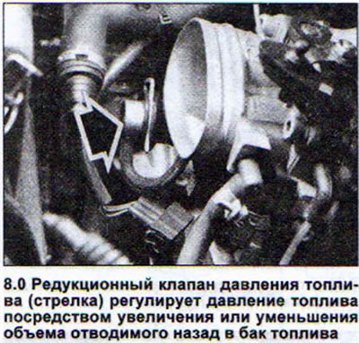
A pressure gauge is required to check the pressure reducing valve and measure the fuel pressure (V.A.G 1318) with a shut-off valve and an adapter. The fuel pressure at idle should be within 2.5 bar, and when disconnecting the vacuum supply hose from the pressure reducing valve, the fuel pressure should increase to almost 3 bar (see illustration 8.0).
Throttle angle position potentiometer
9. Disconnect the potentiometer plug.
10. Connect an ohmmeter to contacts 1 and 2.
12. Open and close the throttle valve and simultaneously monitor the ohmmeter readings. The resistance value should change evenly. A voltage tester with an LED lamp is required to check the injectors.
13. Check the power supply of the injectors. To do this, disconnect the plugs of each injector in order and connect the tester to the contacts of the plug (see illustration).
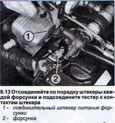
14. Ask an assistant to start the engine. The LED light on the tester should be on. Otherwise, the power supply wire is broken or the Digifant injection system electronic control unit itself is faulty.
15. Disconnect all injector power plugs to check the injectors themselves.
16. Connect an ohmmeter to both contacts of the first injector. The nominal resistance value is 15 - 20 Ohms.
17. Perform the same check on the next injector.
18. Check the injector for leaks and the shape of the injected fuel jet. To do this, remove the injectors together with the fuel distributor. Do not disconnect the power plugs and fuel lines.
19. Disconnect the fuel start valve plug and the coolant temperature sensor plug located on the left side of the outlet pipe.
20. Place the nozzles into the measuring cups.
21. Ask an assistant to operate the starter for a few seconds. The shape of the fuel stream from all four injectors should be the same.
22. Disconnect the common power supply plug to the injectors located on the wiring harness.
23. Turn off the ignition, then turn it on for about 5 seconds. No more than two drops of fuel should flow out of each injector. This is normal.
24. Disconnect the multi-pin connector of the intake air temperature sensor on the air flow meter (see illustration).
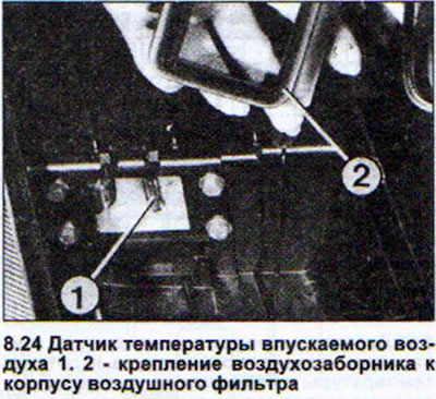
25. Connect an ohmmeter to both outer contacts of the sensor.
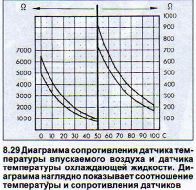
26. Disconnect the blue plug of the coolant temperature sensor in the coolant pipe (see illustration).
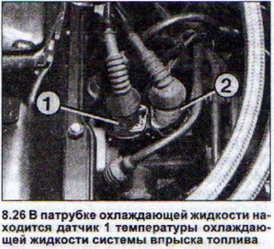
27. Connect an ohmmeter to the sensor contacts.
28. Both sensors. Read the ohmmeter readings.
29. Check using the diagram below that the resistance values of both sensors and the current air and coolant temperatures are within the curves on the right side of the diagram. If not, replace the sensor (see illustration).
30. Disconnect the plugs of all injectors to check the power supply and the functionality of the fuel start valve (see illustration).
31. Disconnect the fuel starter valve power supply plug.
32. Connect the voltage tester with a diode lamp to the valve power plug using the auxiliary wires.
33. Disconnect the coolant temperature sensor plug.
34. Ask an assistant to turn the engine over with the starter. The tester's LED light should light for about 1-4 seconds. If the light does not light, the wiring may be broken or the electronic control unit of the Digifant system may be faulty.
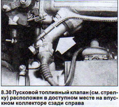
35. Unscrew the starting fuel valve. In this case, the valve power supply plug must be connected, and the injector power supply plugs must be disconnected. Do not disconnect the fuel line from the starting valve either.
36. Disconnect the coolant temperature sensor plug if connected.
37. Lower the fuel starting valve into the container.
38. Ask an assistant to turn the engine over with the starter. The valve should open and deliver fuel for 14 seconds. The shape of the fuel stream should be uniform along its entire length.
39. Wipe the valve dry before checking it for leaks. No gasoline should come out of the valve for a minute and the valve nozzle should not be wet. A gas analyzer is required to check the lambda probe, or the test should be performed in a workshop. The conditions for performing the test correctly and obtaining accurate data are the tightness of the exhaust system, as well as the presence of power at the lambda probe. Make sure that the corresponding fuses are normal.
40. Warm up the engine.
41. Connect the gas analyzer.
42. Start the engine and let it idle for at least two minutes.
43. Increase engine speed to 2000 rpm.
44. Record the readings regarding the CO content.
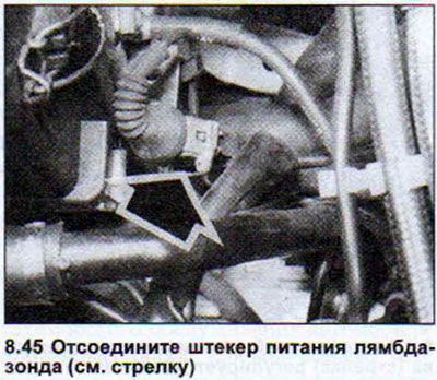
45. Disconnect the low pressure supply hose from the throttle valve pipe. Close the pipe opening with your finger. The CO content should increase for a moment and then drop back to the level that was recorded. If the CO content does not change, disconnect the lambda probe power supply plug (see illustration).
46. Pull the wires from both terminals of the battery and alternately connect them to the plug contact. If the CO content changes, then the lambda probe is faulty. If the CO content remains unchanged in this case, then you need to check the power supply wires to the electronic control unit of the system. If everything is normal here, then the control unit is faulty.
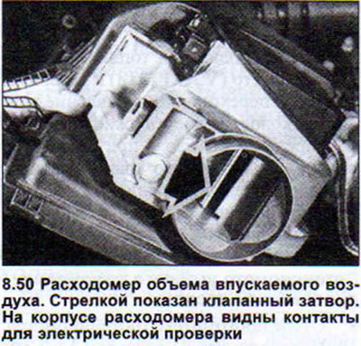
47. Disconnect the air flow meter power supply cable plug. The contacts are numbered from right to left from 1 to 4.
48. Perform a check of the intake air temperature sensor at terminals 1 and 4 as described in paragraph 2429 of this chapter.
49. Connect an ohmmeter to pins 2 and 3 to test the potentiometer.
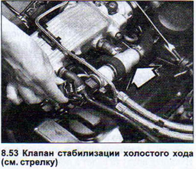
50. Move the valve shutter, watching the ohmmeter readings. The resistance should change (see illustration).
51. Connect an ohmmeter to contacts 3 and 4. The ohmmeter should show resistance between 0.5 and 1 kOhm. If the specified values are not achieved, the flow meter must be replaced.
52. Turn off the ignition before starting the idle speed control valve test. You will hear a hissing sound from the valve. You can also check if it vibrates. If it does not, check the fuses.
53. Disconnect the idle air control valve plug if the fuses are OK (see illustration).
54. Check by connecting a tester with a diode lamp whether voltage is supplied to the contact of the wire with black and blue insulation (ignition on). Close the second contact of the tester to ground. If there is voltage, it means that the valve is receiving power. Now you need to check the valve itself.
55. Connect an ohmmeter and check the resistance at the valve contacts. If the contact is OK, the ohmmeter readings should be within 2-10 Ohms. If the values obtained differ from the nominal values, the valve should be replaced. If the resistance values are normal, the defect may be caused by a wire break or the Digifant system control unit is faulty. To check the unit, workshops use the VAG 1551 reading device. There is no point in taking measurements using other devices.
[The article is a reprint of material from: AudiManual.ru]