
The basic, classic model, the K-Jetronic system, is completely mechanical and functions according to the principle: a large volume of inlet air - a large amount of fuel. However, the use of lambda zones for a regulated catalyst on engines with this injection system without additional equipment was impossible. This was actually the incentive for further improvement of K-Jetronic.
The main components of the system are preserved, but have been supplemented by an electronic control unit and the so-called air-fuel mixture corrector - an electric actuator that additionally regulates the fuel supply. This corrector is usually activated when the engine warms up, but at the same time performs its main function concerning the composition of the air-fuel mixture.
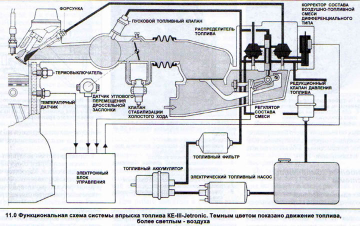
Together with the fully electronic ignition system, this injection system is an engine control unit. Despite the fact that both of these systems have their own control units, information is constantly exchanged between them. In addition, the information required for ignition and fuel injection comes from the same sensors. A self-diagnostic system with a data storage device for past malfunctions completes the list of electronic innovations introduced into the basic model (see illustration 11.0).
Main components of the system
Throttle valves
There are two throttle valves on one pipe in the intake manifold. The smaller of these valves is connected by a gas cable to the accelerator pedal (see illustration 11a).
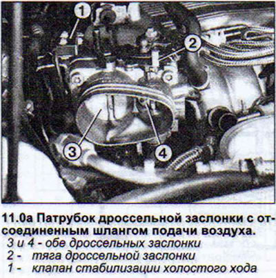
Until the accelerator pedal reaches the "Full throttle" position, this valve doses the intake air. And only when the accelerator pedal is sufficiently pressed does the corresponding rod open the second valve of a larger diameter.
Air-fuel mixture regulator
This is the main component of this fuel injection system. It consists of an intake air volume meter and a fuel distributor (see illustration 11.0b).
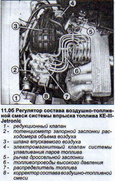
The principle of its operation is as follows. The shut-off valve of the air flow meter, made of light metal, is located in the path of the incoming air flow. Under the pressure of the air flow, it opens. The angle of its opening is greater, the more air enters through the throttle valve. Through a system of levers, the amount of deviation of the shut-off valve is communicated to the fuel distributor (see illustration 11.0b).
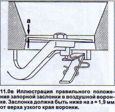
The flap should be lower by a = 1.9 mm from the top of the narrow edge of the funnel. If necessary, the flap position can be adjusted by bending the spring (see illustration 11.0b).
Note: The newest types of air flow meters have an adjustment screw instead of a spring, allowing for more precise adjustment.
The main parts of the fuel distributor are the distribution piston and the cylinder window through which the fuel enters the injector. The distribution piston closes or opens this window and lets in fuel proportionally to the degree of deviation of the air flow meter shut-off valve.
Fuel pressure in the system
The fuel pump in the fuel tank supplies fuel under pressure to the injection system. On the fuel flow path there is a fuel pressure reducing valve installed in the housing. This valve removes excess pressure, leaving a pressure of 6.1-6.5 bar in the system.
Differential type air-fuel mixture corrector
The corrector is responsible for the ratio of air and fuel in the air-fuel mixture. The corrector works as follows. The fuel flow to the lower chambers, from which the mixture composition can be adjusted, passes through the corrector. Accumulating in the lower chambers, the incoming fuel creates a certain pressure there. The strength of this pressure depends in turn on the volume of fuel passed by the corrector. The corrector membrane reacts to the pressure drop by bending towards the holes through which the fuel enters the injector, blocking it to a greater or lesser extent. Thus, a smaller or larger amount of fuel enters the injectors, providing the desired composition of the air-fuel mixture.
The air-fuel mixture corrector receives the corresponding "instructions" from the control unit, which responds accordingly to information from the lambda probe, coolant temperature sensor and, in general, to the operating load on the engine.
The air-fuel mixture corrector is located on the side of the mixture regulator. The corrector is an additional element of the regulator's operation, which continues to operate even if the electronics fail.
Nozzles
The injectors inject fuel into the intake port in front of the intake valve of the corresponding cylinder as soon as the fuel pressure rises to 4.3-4.6 bar. The injectors open up to 2000 times per second, ensuring a high degree of fuel atomization.
Electronic control unit
The electronic control unit of the system through the air-fuel mixture corrector provides the required mixture composition for the engine at the current moment. To control this process, the unit requires information about the engine temperature, the number of revolutions, the engine starting conditions, the position of the air flow meter shut-off valve, and the engine operating mode (idle, full load). This information is supplemented by the corresponding signals from the lambda probe, as well as additional information from the ignition system, altitude corrector and automatic transmission. The electronic control unit, like all other AUDI 80 models, is located in the passenger compartment, on the right side, between the air supply channel from the heater and the dividing wall between the passenger compartment and the engine compartment.
Idle speed control valve
This valve opens a channel for air to flow bypassing the throttle valve. The essence of this method is as follows. The air flow meter "believes" that the air volume has increased as a result of opening the throttle valve and provides a corresponding increase in the injected fuel. As a result, the engine speed increases. The volume of additionally admitted air is determined by the KE-III-Jetronic system control unit, based on the current engine speed. Thus, the electronics strive to bring the engine speed to nominal values.
Fuel starter valve
The starting fuel solenoid valve is an injector that, when starting the engine, depending on its temperature, briefly injects fuel into the intake manifold, spraying it at the same time. The injection duration is set by the KE-III-Jetronic system control unit.
Throttle Position Sensor
AUDI 80 cars are equipped with two throttle angle sensors. These sensors provide the following information:
- Idle mode. Idle speed control, forced idle speed, operation of the fully electronic ignition system in this mode, etc.
- Full load. Enrichment of the air-fuel mixture and operation of the fully electronic ignition system.
Forced idle mode
When driving in this mode, the mentioned air-fuel mixture corrector shuts off the fuel supply. The electronic control unit recognizes this driving mode based on information that the engine speed is greater than the idle speed and that the throttle valve is closed.