
Table of contents: Injection system components -… ↓ Injectors - removal ↓
A car enthusiast is not able to perform the overwhelming majority of possible injection system checks on his own, because these checks must be performed using special control and measuring devices. The electronic control unit cannot be checked using the devices available to the car enthusiast. As practice shows, control unit failure occurs only in rare cases. Sensors, valves, and plugs fail much more often. If a defect occurs in the fuel injection system, we recommend the following procedure:
1. Make sure the ignition system is normal.
2. Check the power supply system.
3. Visually check the condition of the fuel injection system components. If the cause of the malfunction has not been determined after performing the above actions, then read the list of possible malfunctions of the fuel injection system and methods for eliminating them, and also contact the workshop to print out the malfunction codes registered by the control unit.
4. Check the condition of the hoses in which air circulates. Check absolutely all air hoses, starting from the thick air intake hose and ending with the thinnest one, related to the low-pressure supply system.
5. Make sure that the gaskets of the starting fuel valve, injectors, and the sealing gaskets on the intake manifold mounting flanges are normal. A leaky intake manifold results in "side" air entering the system. The amount of this air is not included in the parameters stored in the memory of the electronic control unit and leads to a malfunction of the system. Excess air leads to an uncontrolled depletion of the air-fuel mixture. This defect is especially noticeable when the engine is idling due to fluctuations in the speed.
6. Make sure the fuel lines are securely fastened and have a tight fit.
7. Make sure that the connector plugs are seated properly and that the contacts are not broken or bent. If necessary, spray the contacts with an aerosol to improve the conductivity of the contacts. Do not bend the contacts themselves.
Injection system components - checking
Attention! When working on the KE-111-Jetronic fuel injection system, remember that the fuel system remains under pressure for a long time even after the engine has stopped. Therefore, when disconnecting the fuel line, always cover it with a rag to prevent fuel from getting into your eyes.
The following procedure for detecting and eliminating defects applies only to those works that do not require the use of special tools and measuring instruments.
Nozzles
8. Turn off the ignition.
9. Disconnect the fuel line to ensure that fuel is reaching the injector.
10. Keep a rag handy as fuel is usually ejected from the fuel line.
11. Ask an assistant to operate the starter if no fuel comes out of the fuel line after disconnecting it. If fuel comes out when the starter is operated, then the fuel line is normal and fuel is supplied to the injector. Therefore, it is necessary to check the injector itself.
12. Remove the injector. First remove the upper part of the intake manifold.
13. Place a container or rag underneath to collect any leaking fuel.
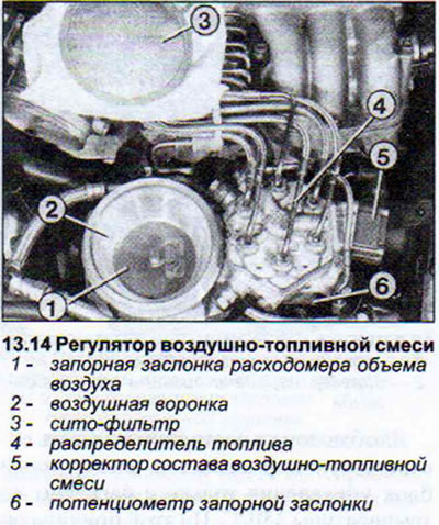
14. Remove the large diameter air hose located between the air/fuel mixture regulator and the throttle body. This will provide access to the shut-off valve on the air flow meter (see illustration).
15. Disconnect the fuel pump relay at the switch panel 10.
16. On the switchboard 10, jumper contacts 48 (or 30) and 52 (or 87) using a piece of wire. The fuel pump should start working.
17. Move the shut-off valve by hand at a small angle. The injector should inject fuel. The fuel stream should be cone-shaped. If this does not happen, try again, this time move the shut-off valve to the stop. In the same way, you can check the amount of fuel injected by each injector. When performing this check, insert all the injectors into measuring cups. Do not bend the fuel lines of the injectors.
18. Open the shut-off valve approximately 2 mm.
19. Do not remove the jumper on the switch panel until approximately 20 cc (ml) of fuel has collected in the first measuring cup.
20. Compare the amount of fuel in the cups. The difference in volume should not exceed 2.5 cm³.
If this difference is greater, then swap the injector with a larger and smaller injection volume and repeat the test. If swapping the injectors does not help and one of the injectors still injects more fuel, then replace this injector.
If, after replacing the injectors, the same result is observed, then the reason for this may be a clogged fuel line, due to which its opening has become smaller, or the fuel distributor is faulty.
21. Perform a leak test of the injectors. After turning off the fuel pump (remove the jumper from the relay switchboard) after two minutes of operation with the shut-off valve on the air flow meter open, no fuel should come out of the injectors.
Fuel starter valve
22. Turn off the ignition.
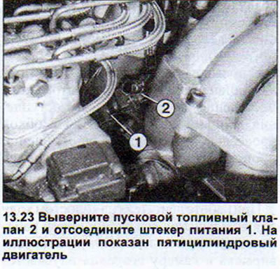
23. Unscrew the starting fuel valve and disconnect the power plug. Do not disconnect the fuel line from the valve (see illustration).
24. Turn on the starter to make the fuel pump operate and increase the pressure in the system.
25. Lower the starting fuel valve into the container and connect an auxiliary wire to its contacts.
26. Connect the free ends of the auxiliary wires to the battery terminals, one to (+) and the other to (-). The valve should start injecting fuel, which should come out in the form of a cone-shaped stream.
27. Perform a leak test of the valve closure. To do this, turn on the starter again to create pressure in the system.
28. Wipe the valve dry. No fuel should come out of it for a minute.
Fuel distributor
29. Start the engine for about 10 seconds or operate the starter to increase the pressure in the fuel system.
30. Remove the air filter cover and take out the replaceable filter element.
31. Disconnect the air hose attached to the mixture regulator and to the throttle valve pipe.
32. Move the air flow meter shut-off valve all the way up. It should open with equal resistance along the entire opening path.
33. Release the flap. It should close and there should be no resistance to its closing. Otherwise, the air flow meter must be replaced. If the shut-off flap is difficult to open, but closes easily, this means that the distribution piston is stuck in the fuel distributor.
34. Replace the fuel distributor.
Air flow meter
35. Warm up the engine or let the still warm engine run for about 10 seconds before performing the check.
36. Disconnect the air hose secured to the mixture regulator and to the throttle valve pipe, having first loosened the fastening clamps.
37. Check the air flow meter shut-off valve. The valve should be 1.9 mm lower than the top of the narrow edge of the funnel, when viewed from the fuel line mounting side. The maximum allowable distance can be 3 mm (see illustration 11.0b). If necessary, adjust the position of the damper by bending the retaining wire spring. Do not bend the leaf spring.
38. Make sure that the flap does not catch on the wall of the funnel after adjustment. If so, center it by loosening the mounting screw.
After making the above adjustments, check the idle speed and CO content.
Idle speed control valve
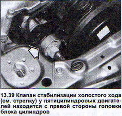
39. Turn on the ignition and touch the valve with your hand. The working valve vibrates noticeably. If this is not the case, then either the valve itself is faulty, or the electronic control unit of the KE-III-Jetronic fuel injection system (see illustration).
40. Check the valve. To do this, disconnect the power plug and connect an ohmmeter to the valve contacts. The device should show a slight resistance. If the ohmmeter shows infinite resistance, this means the winding is broken and the valve must be replaced.
If the valve is normal, then the reason for its failure may be a break in the power supply wire or a malfunction of the electronic control unit of the system.
41. Connect a tester with a diode lamp to the contacts of the disconnected valve plug to check the power supply.
42. Turn on the ignition. If the light comes on, it means that power is supplied to the valve from the fuel injection system control unit.
Throttle Position Sensors. Vehicles with Manual Transmission
It is impossible to connect the ohmmeter directly to the sensors themselves, especially since one of them is located under the throttle valve pipe. Therefore, only the power supply is disconnected and measurements are performed on the sensor power supply wires.
43. Idle speed sensor. Connect an ohmmeter to pins 1 and 2 of the plug. When the throttle valve is in the idle position, the ohmmeter should show 0 ohms.
44. Open the throttle valve slightly. The ohmmeter should show infinite resistance (G).
45. Full throttle position sensor. Connect an ohmmeter to terminals 2 and 3. When the throttle is in the "Full throttle" position, the ohmmeter should read 0 ohms.
46. Close the throttle valve. The ohmmeter should show infinite resistance (G).
Throttle Potentiometer. Cars with Automatic Transmission
47. Disconnect the three-pin throttle potentiometer connector.
48. Connect an ohmmeter to contacts 1 and 2. The ohmmeter should show 1.5-2.6 kOhm.
49. Connect an ohmmeter to contacts 2 and 3. The ohmmeter should show 0.75-1.3 kOhm.
50. Open the throttle valve. The ohmmeter should remain connected and show a resistance of no more than 3.6 kOhm.
Attention! The throttle potentiometer can be adjusted. However, after the appropriate adjustment has been made, the automatic transmission must also be "tuned". This adjustment can only be performed in a workshop.
Coolant temperature sensor
AUDI 80 vehicles with the KE-III-Jetronic fuel injection system are equipped with a dual-purpose coolant temperature sensor. This sensor is also included in the ignition system circuit (see illustration 13.0).

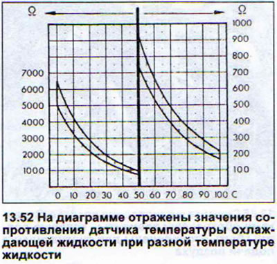
51. Connect the ohmmeter to one of the contacts, and connect the other terminal of the ohmmeter to the "ground" (-), for example, to the cylinder block. The obtained value will depend on the temperature.
52. Compare the obtained value with the data in the diagram (see illustration).
Lambda control mechanism
Checking the lambda control mechanism is quite simple. But you need an adapter and an ammeter. The check can also be done using a gas analyzer. Below is the procedure for checking using an ammeter. The check should be done with a warm engine.
53. Disconnect the air-fuel mixture corrector plug.
54. Connect the adapter, which you can make yourself from two corresponding plugs and a piece of wire, to the power cord and to the corrector.
55. Separate one of the adapter wires and connect it to the ammeter (milliamp range).
56. Start the engine and let it idle.
57. Write down the value shown by the ammeter.
58. Pull out the engine oil level indicator rod (dipstick). The current in the control circuit must increase. If this is not the case, then one of the lambda control components is faulty. To clarify this, disconnect the plug of the lambda probe and connect the green insulated wire leading to the electronic control unit to the "ground" (-) for about 20 seconds. If the control circuit current changes, then the KE-III-Jetronic fuel injection control unit is in good condition, and the lambda probe has the correct temperature. a defect. If the current in the control circuit does not change, then the control unit is faulty.
Attention! The main condition for the correct functioning of the lambda control mechanism is the correct adjustment of the idle speed.
The procedure for removing most parts related to the fuel injection system does not require detailed explanations. Explanations are only necessary for removing the injectors, air supply hose and upper part of the intake manifold.
Injectors - removal
59. Remove the upper part of the intake manifold.
60. Disconnect the injector holder.
61. Remove the injector with pliers together with the insert. Do not disconnect the fuel lines to prevent dirt from getting into the injectors.
62. Lubricate the rubber sealing rings with gasoline before installing the injectors in place, so that they go into place more easily. If the injector is installed "dry", it is possible that the sealing rings may twist and they will not provide the necessary tightness of the injector seat. In this case, the engine will run unevenly, which is caused by air "sucking in", for example, at idle.
63. Be sure to replace damaged or brittle rubber rings.
64. Tighten the holder mounting bolts to a torque of 10 Nm.
The air supply hose, which is attached to the air-fuel mixture regulator and the throttle valve pipe, is removed either partially or completely when performing many jobs.
65. Loosen the hose clamps on the air-fuel mixture regulator and on the throttle valve pipe (see illustration).
66. Loosen the clamps securing the remaining air hoses. These include: the air supply hose to the idle speed control valve, to the injector air duct. Remove these hoses as well.
67. Disconnect the fuel vapor recovery system valve.
68. Remove the air supply hose. When installing the hose, do not forget to place the filter screen on the fuel mixture regulator. The convex side of the screen should be facing up.
To remove the upper part of the intake manifold, you also need to disconnect the air supply hose.
69. Disconnect the gas cable and remove it from the counter support (see illustration).
70. Disconnect the throttle position sensor plug.
71. Remove all remaining air hoses.
72. Remove the intake manifold top mounting bolts and remove it.
72. Replace the old gaskets with new ones before installing the intake manifold.
73. Tighten the intake manifold top mounting bolts in two passes to 20 Nm.
[The original publication in its entirety is posted on the website AUDIMANUAL.ru]