
The survey and printout of registered faults can only be performed in a workshop using the VAG 1551 device.
Attention! Electronic control unit of the MPFI injection system (2.6L engine) remains active for another hour and a half after the ignition is switched off. This means that a malfunction in the injection system that occurs during this time is registered by the unit. At the same time, there is no need to wait until the hour and a half has passed in order, for example, to check one of the sensors. The system, accordingly, will register the disconnection of the sensor power plug, but such a "malfunction" is a one-time event and, as indicated above, it will be automatically deleted.
Due to the need to use special control and measuring devices, most fuel injection system checks are not available to the car owner. However, some checks can be easily performed by the car owner himself.
The electronic control unit cannot be checked using the devices available to the car enthusiast. But, as practice shows, the control unit fails only in rare cases. Sensors, valves, and plugs fail much more often. If a defect occurs in the fuel injection system, we recommend the following procedure:
1. Check that all injection system fuses are normal (No. 13, 21, 27, 28 and 32).
2. Make sure the ignition system is normal.
3. Check the power supply system.
4. Visually check the condition of the fuel injection system components. If the cause of the malfunction has not been established after performing the above actions, then read the list of possible malfunctions of the fuel injection system and methods for eliminating them, and also contact the workshop to print out the malfunction codes registered by the control unit.
Attention! Reading of registered faults is possible only if the battery has not been disconnected before. When the battery is disconnected, all data is deleted from the storage device.
6. Check the condition of the hoses in which air circulates. Check absolutely all air hoses, starting from the thick air intake hose and ending with the thinnest one, through which the reduced pressure is supplied to the pressure reducing valve.
7. Make sure that the gaskets of the starting fuel valve, injectors, and the sealing gaskets on the intake manifold mounting flanges are normal. A leaky intake manifold results in "side" air entering the system. The amount of this air is not included in the parameters stored in the memory of the electronic control unit and leads to a malfunction of the system. Excess air leads to an uncontrolled depletion of the air-fuel mixture. This defect is especially noticeable when the engine is idling due to fluctuations in the speed.
8. Warm up the engine and let it idle. Open the hood and disconnect the lambda probe plug.
9. Spray from an aerosol can with the so-called starting fluid (for example, "Startpilot") injection system unit in the flange area on the intake manifold side, as well as other places of suspected leaks.
If, when applying the specified liquid to a certain part, the engine speed increases, then this is the place where air is being sucked in.
10. Make sure that the connector plugs are seated properly and that the contacts are not broken or bent. If necessary, spray the contacts with an aerosol to improve the conductivity of the contacts. Do not bend the contacts themselves.
Injection system components - checking
If you suspect that one of the injectors is not working, you can check it using a tester with a diode lamp and an ohmmeter.
11. Disconnect the plugs of all injectors.
12. First check the power supply to the injectors. To do this, connect a tester with a control diode lamp to the contacts of the injector plug (see illustration).
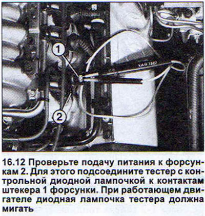
13. Start the engine. The LED should blink. Otherwise, there is no power supply to the injector or the control unit has a bad "ground" (-).
14. Check the resistance of the injectors by disconnecting all the plugs.
15. Connect the ohmmeter to the injector contacts. If the engine is cold, the injector resistance should be 13.5-17 ohms. If the ohmmeter readings are outside the specified data, the injector must be replaced.
16. Check the tightness of the injector closure. To do this, remove the fuel distribution line together with the injectors.
17. Disconnect the injector plugs, but do not disconnect the fuel lines from the injectors.
18. Ask an assistant to turn the engine over several times with the starter to activate the fuel pump and build up pressure in the system.
19. Watch the injectors. No more than 1-2 drops of fuel should flow out of each injector per minute. Otherwise, replace the corresponding injector.
20. Check the shape of the jet of fuel injected by the injector and the volume of this fuel, if necessary.
21. Disconnect the throttle position potentiometer plug to check it.
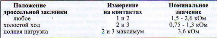
22. Measure the resistance at the potentiometer contacts using a highly sensitive ohmmeter. Measurements are taken with the throttle valve in the "Idle" and "Full Load" positions. The engine must be turned off when taking measurements. The data obtained must be within the values given in the table.
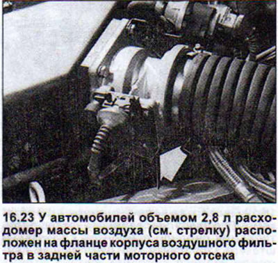
23. Slide the rubber cuff of the air mass flow meter plug (vehicles with MPI fuel injection system). Do not disconnect the plug itself (see illustration).
24. Connect a highly sensitive voltmeter to the contact connections on the back of the plug.
25. Perform measurement #1. Connect the voltmeter to contacts 2 and 3 of the air mass meter plug.
26. Turn on the ignition. The voltmeter should register 12-14 V. If the received data does not match the specified data, then there is a break in the power supply line.
27. Check fuse #27, as well as the wire leading from fuse #27 to contact 3 of the air mass meter plug, or the ground (-) wire and its connection to contact 2 of the plug and the cylinder block.
28. Perform measurement #2. Connect the voltmeter to terminals 2 and 4.
29. Turn on the ignition. The voltmeter should register a voltage of 1.0-7.5 V. Otherwise, the air mass meter must be replaced.
30. Perform measurement #3. Connect the voltmeter to terminals 1 and 2.
31. Turn on the ignition. The voltmeter should show 0.3-1.1 V.
32. Start the engine. The voltmeter remains connected.
33. Switch off all electrical consumers of the on-board network. The radiator fan should also not work.
34. Maintain the engine speed between idle and 4000 rpm. Depending on the current engine speed, the voltmeter should register readings of 1.5-3.4 V (maximum). Otherwise, replace the air mass flow meter, as it is faulty.
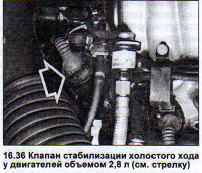
The idle speed control valve for the 2.8 liter engine is located on the right side of the throttle body. You can check the valve as follows:
35. Disconnect the idle speed control valve plug and connect a highly sensitive ohmmeter to both contacts of the valve. The ohmmeter should show 7-11 ohms. Otherwise, the valve is faulty.
36. Disconnect the idle air control valve for further testing. Do not disconnect the valve plug (see illustration).
37. Set the rotating piston of the valve inlet to the "Open" or "Closed" position. Do not use a metal tool for this!
38. Turn on the ignition and watch the piston rotate. It should move and be located approximately in the center.
39. Check the ease of movement of the piston. When the removed valve is turned sharply, the piston should move. In addition, it should not have any scoring or signs of wear.
Attention! Idle speed control valve for 2.6 liter engines (mPFI fuel injection system) cannot be removed independently. Otherwise, after installing the valve, it will be necessary to perform the so-called basic adjustment, which is only possible with the VAG 1551 device, which is only available in AUDI repair shops. In addition, if the idle speed stabilization valve plug is disconnected earlier than an hour and a half after the last engine start, the self-diagnosis system will register a valve malfunction, which may not actually be true.
For this reason, in vehicles with the MPFI fuel injection system, you can only independently check the idle speed control valve winding.
40. Disconnect the idle speed control valve plug (see illustration).
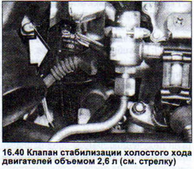
41. Using a sensitive ohmmeter, measure the valve resistance at contacts 1 and 4, as well as 2 and 3. If the valve is working properly, the ohmmeter should show 45-60 Ohms.
Other valve checks cannot be performed independently.
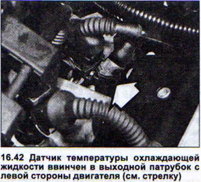
If the engine malfunctions when it reaches a certain temperature, the cause may be a defective coolant temperature sensor.
Warning! If the 2.6L engine coolant temperature sensor plug is disconnected earlier than one and a half hours after the last engine start, the self-diagnostic system will register a sensor malfunction, which may not actually be the case.
42. Disconnect the coolant temperature sensor plug (see illustration).
43. Measure the resistance on both sensor contacts using a highly sensitive ohmmeter. Compare the obtained data with the table of nominal values (see illustration).
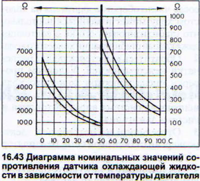
The obtained data depends on the engine temperature. If they go beyond the values inside the curves on the diagram, the coolant temperature sensor must be replaced. The following data can be used as reference values: at a coolant temperature of 20°C, the ohmmeter should show a resistance of approximately 2.5 kOhm, and at a coolant temperature of 80°C - approximately 330 Ohm.
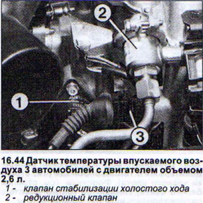
The intake air temperature sensor is only available on vehicles with a 2.6L engine. It is located on the right side of the engine next to the idle speed control valve and the pressure relief valve.
Caution! If the 2.6L engine intake air temperature sensor plug is disconnected earlier than one and a half hours after the last engine start, the self-diagnosis system will register a sensor malfunction, which may not actually be the case.
44. Disconnect the intake air temperature sensor connector (see illustration).
45. Measure the resistance on both sensor contacts using a highly sensitive ohmmeter. Compare the obtained data with the table of nominal values (see illustration).
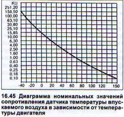
The data obtained depends on the engine temperature. If they go beyond the values inside the curves on the diagram, the intake air temperature sensor must be replaced. The following data can be used as reference values: at a coolant temperature of 20°C (room temperature, engine cold) the ohmmeter should show a resistance of approximately 6.3 kOhm.
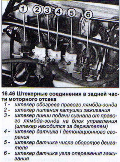
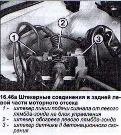
46. Disconnect the plug on the lambda probe power wire to check it (see illustrations 16.46 and 16.46a). A highly sensitive ohmmeter is required for measurements
47. Check the lambda probe heating.
48. Disconnect the probe heating plug and connect an ohmmeter to both probe contacts. The resistance of a working sensor is 3-15 ohms. If this is not the case, replace the probe.
49. Check the probe. To do this, disconnect the probe plug and connect one connecting wire of the ohmmeter to the probe contact, and the second to the "ground" (-). If the probe is working properly, the ohmmeter should show infinite (I) resistance. Otherwise, replace the lambda probe.
50. Check the wire transmitting the probe signal to the control unit. To do this, disconnect the probe plug and connect one connecting wire of the voltmeter to the probe contact, and the second to the "ground" (-). If the probe is in good condition, the voltmeter should show 0.35 - 0.45 V. Otherwise, check the wire. If the wire and its connection are normal, replace the control unit.
To replace the lambda probe, you need to disconnect the plugs and loosen the wire clamps.
51. Lubricate the threads of the new lambda probe with paste before installing it. Do not allow the paste to get into the probe splines. The tightening torque of the probe is 50 Nm.
The procedure for removing most parts related to the fuel injection system does not require detailed explanations. Additional explanations are only necessary for removing the air mass flow meter and injectors.
To remove the air mass flow meter, loosen the air intake hose clamp, disconnect the air mass flow meter power plug and remove the upper part of the air filter together with the air mass flow meter.
Fuel Injectors - Removal
52. Remove the air hose between the air filter (air flow meter) and the engine.
53. Disconnect the high voltage wires and set them aside from the work area.
54. Disconnect the injector plugs.
55. Disconnect the fuel distribution line from the intake manifold.
56. Remove the low air pressure hose from the fuel pressure reducing valve.
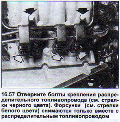
57. Remove the fuel distribution line together with the six injectors by pushing it upwards (see illustration).
58. Disconnect the injector retaining clips and remove the injectors.
59. Replace all O-rings on all injectors and lubricate them with engine oil before installation.
60. Install the injectors in place. When installing, be careful not to screw in the sealing ring or damage it.
(This article was previously published on the resource AUDIMANUAL.RU)