General description
The AUDI 80 petrol engines have a fuel injection system through one nozzle under the throttle valve, developed by BOSCH and named "Mono-Motronic". The system is a unit that consists of a housing resembling a carburetor in shape and one injector. Fuel injection by the injector is determined by an electronic control unit, which simultaneously regulates the ignition timing.
The electronic fuel injection control unit is located in the passenger footwell. The control unit receives information from the following injection controls via a multi-pin connector:
- the Hall sensor on the ignition distributor supplies information about the engine speed,
- the lambda probe on the catalytic converter informs the control unit about the oxygen content in the exhaust gases,
- the throttle angle potentiometer provides information on the position of the throttle valve and, accordingly, on the volume of fresh air supplied,
- the intake air temperature sensor at the inlet of the injection system reports the temperature of the air taken in,
- the coolant temperature sensor on the outlet pipe on the left side of the cylinder head provides information on the current coolant temperature.
Based on the information received, the electronic control unit calculates the duration of the injector opening and, accordingly, the amount of fuel injected. In doing so, the control unit uses the parameters stored in its memory, obtained during engine tests and representing all conceivable situations that may arise during engine operation. These parameters contain data on the volume of fuel required by the engine in the corresponding situation. This information is electrical signals. Along with data concerning the volume of fuel and operating loads, the aforementioned parameters contain information on the ignition advance angles in relation to the corresponding situation.
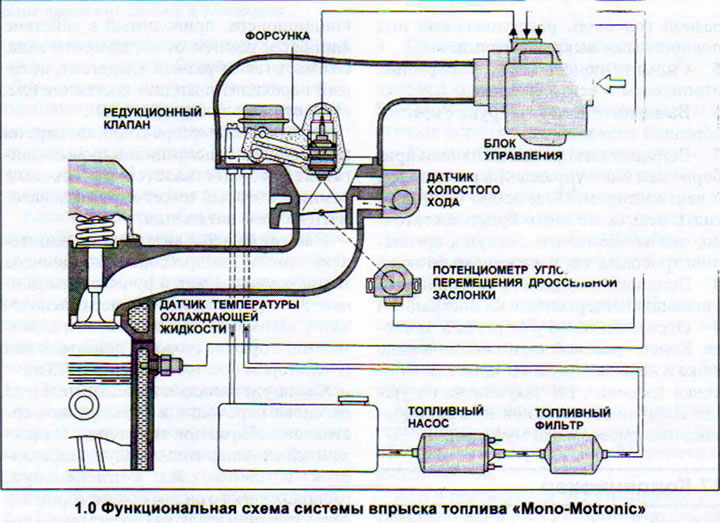
The throttle valve is located at the bottom of the fuel injection system and regulates the amount of air sent to the engine for combustion. The driver determines the degree of opening of the valve by the force applied to the accelerator pedal. The throttle valve and the accelerator pedal are connected to each other by a cable (see illustration 1.0).
Most of the functional elements of the fuel injection system are combined in one housing. The air that is supplied to form the air-fuel mixture also passes through the housing of the system. Here, fuel is injected through the nozzle, similar to how the carburetor used to do it (see illustration 1.0a).

The injector is opened by an electromagnet and, depending on the command from the control unit, fuel can be supplied. For optimal fuel dispersion, the injector has inclined outlet holes, from which the fuel is broken up against a conical wall at the outlet and simultaneously swirls.
The injector can only open and close. It does not dose the injected fuel. For this reason, the amount of injected fuel varies by the injection duration. This happens as follows: With each pulse received from the Hall sensor, the injector injects fuel. If little fuel is needed, the injector opens only briefly when receiving a pulse from the Hall sensor. The injector opening duration is often less than one thousandth of a second. If the engine needs more fuel, for example, when starting in a cold state or at full operating load, the injection lasts longer. This happens with each pulse received from the Hall sensor.
The fuel pump delivers fuel under pressure to the pressure reducing valve (see illustration 1.0b).
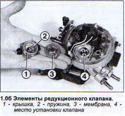
This valve is designed to provide constant fuel pressure at the fuel injector within 0.8-1.2 bar. To this end, it diverts excess fuel back into the fuel tank, feeding fuel into the return fuel line. The volume of fuel supplied by the fuel pump remains generally constant.
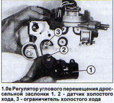
The throttle position controller is a small electric motor with an angular transmission that moves the throttle lever relative to the idle speed limiter depending on the need. This ensures a constant idle speed at different operating loads. In the front part of the throttle lever there is an idle speed sensor that sends a corresponding signal to the electronic control unit when the driver removes his foot from the accelerator pedal. The control unit needs this signal to stabilize the idle speed. The throttle position controller can be removed. This is necessary, in particular, if a defect occurs in the throttle lever on which the idle speed sensor is attached (see illustration 1.0v).
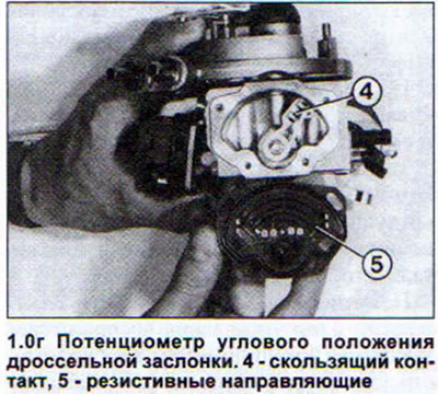
The throttle angle potentiometer informs the control unit of its current position. Rapid opening of the throttle valve is recognized as a signal for acceleration and increase in speed. As soon as the driver removes his foot from the accelerator pedal, the signal to close the throttle valve is also a signal to turn off the force aimed at opening the valve. Information is transmitted using electrical signals, because the potentiometer is nothing more than a modified resistor. The throttle angle potentiometer has a factory adjustment and cannot be disassembled. In case of a potentiometer defect, the injection system unit must be replaced as a set. In Illustration 1.0g, the potentiometer is specially shown disassembled for clarity.