1. Make sure the ignition is normal.
2. Check the fuel system.
3. Visually check the condition of the fuel injection system components.
If the cause of the malfunction has not been determined after performing the above actions, then review the list of possible malfunctions of the fuel injection system and methods for eliminating them, and also contact the workshop to print out the malfunction codes registered by the control unit. Based on the data obtained, determine the cause and check the corresponding part.
Caution! In the event of a sudden complete failure of the fuel injection system, first check fuses No.13, 21, 25, 27 and 28. They supply power to the Mono-Motronic system.
A leaky intake manifold results in "side" air entering the system. The amount of this air is not included in the parameters stored in the memory of the electronic control unit and leads to a malfunction of the system. Excess air leads to an uncontrolled depletion of the air-fuel mixture. This defect is especially noticeable when the engine is idling due to fluctuations in the speed. In such cases, high-pitched detonation knocks appear when the engine is fully loaded.
4. Check the condition of the hoses intended for supplying low pressure, as well as their fastenings. It is necessary to check all hoses on the injection system and the intake manifold (brake booster hose, heated air supply hose, fuel vapor recovery system hoses).
5. Warm up the engine and let it idle. Open the hood.
6. Spray from an aerosol can with the so-called starting fluid (for example, "Startpilot") injection system unit in the flange area on the intake manifold side, intake manifold pipe seals, and hoses of units generating low pressure. Disconnect the lambda probe plug. If the engine speed increases when applying the specified liquid to a certain part, this is the place where air is sucked in.
7. Make sure the fuel hoses are tight.
8. Make sure that the connector plugs are seated properly and that the contacts are not broken or bent. If necessary, spray the contacts with an aerosol to improve the conductivity of the contacts. Do not bend the contacts themselves.
Injection system components - checking
Throttle position controller
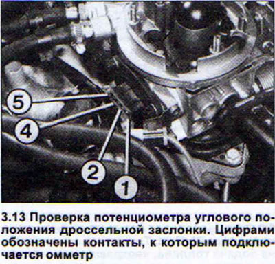
7. Disconnect the throttle position adjuster plug.
8. Apply a maximum of 6 V to the connecting contacts of the regulator plug. The positive charge supply wire (+) must be connected at the top. For a four-pole plug, these are contacts 1 and 2 (both top), and for a six-pole one - 1 and 6 (top and bottom). The pusher should move back completely.
9. Reverse the polarity of the power supply. The negative (-) supply wire should now be on top. The plunger should come all the way forward.
If the regulator plunger functions as expected when this test is performed, the regulator is OK. Otherwise, replace the regulator.
Additionally, you can check the resistance of the winding of the actuator motor of the regulator. On the mentioned contacts, the resistance should be 3-200 P.
Idle speed sensor
10. Disconnect the throttle position adjuster plug.
11. Connect an ohmmeter to the idle speed sensor contacts. For a four-pin plug, these are contacts 3 and 4 (both bottom), and for a six-pole one - 4 and 5 (counting from top to bottom).
Attention! In case of replacement of the throttle valve angular movement regulator, it is necessary to adjust the idle speed sensor. The work is performed in the workshop.
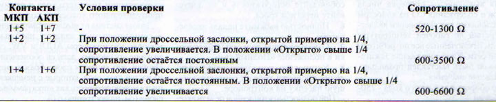
Throttle angle position potentiometer
12. Disconnect the throttle angle potentiometer plug.
13. Connect the ohmmeter to the pairs of contacts as indicated in the table. If the data obtained during the measurement do not correspond to those given in the table, then the potentiometer is faulty and must be replaced. Considering that the potentiometer is non-separable, then for this you should replace the entire lower part of the injection system unit (see illustration).
Nozzle
Check with the engine running. The engine oil temperature must be at least 60°C, which corresponds to a 10-minute drive performed immediately after starting a cold engine.
14. Remove the air intake pipe.
15. Start the engine and let it idle.
16. Pay attention to the shape of the fuel jet from the injector. It should be the same along its entire length and should exit in the direction of the throttle valve.
17. Turn off the engine to check the tightness of the nozzle closure. With the engine turned off, no more than two drops of fuel per minute should come out of the nozzle.
The following steps are performed if the engine does not start.
18. Check fuses 13 and 27.
19. Remove the air filter or air intake pipe.
20. Ask an assistant to turn the engine over with the starter.
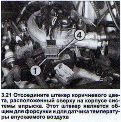
21. Monitor the injector and make sure it supplies fuel to the system. If this does not happen, disconnect the brown plug located on the top of the injection system housing (see illustration).
22. Connect the ohmmeter to both middle contacts of the part of the plug that remains on the system body. At an air temperature of +15 - +30°C, the injector resistance should be 1.2-1.6 Sigma. If the readings are different, the injector is faulty.
23. Unscrew the screw with an internal hexagon and replace the injector.
24. Check the injector power supply, if the injector resistance is normal.
25. Connect the voltage tester with the diode lamp (do not connect other devices) to both middle contacts of the disconnected part of the plug.
26. Start the engine. The LED lamp should light. Otherwise, there is a break in the power supply wire or a defect in the control unit.
Forced idle mode
27. Remove the air filter or disconnect the air intake pipe.
28. Start the engine and increase the speed to 3000 rpm, then at these speeds release the gas (close the throttle valve).
29. Monitor the operation of the injector. When the throttle valve closes, the jet of injected fuel should be interrupted for a while. This means that the forced idle mode is normal. If this is not the case, check the throttle valve angular movement regulator and the electronic control unit (in the workshop).
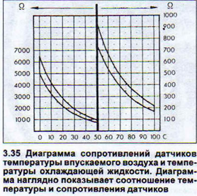
Coolant and intake air temperature sensors
30. Intake air temperature sensor. Disconnect the brown connector on the fuel injection system housing.
31. Connect an ohmmeter to both external contacts of the sensor.
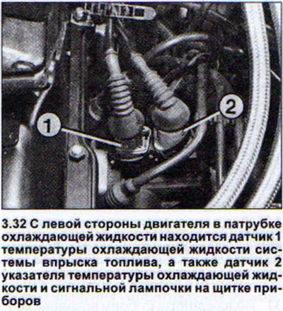
32. Coolant temperature sensor. Disconnect the blue two-pole sensor plug in the coolant pipe (see illustration).
33. Connect an ohmmeter to the sensor contacts.
34. Both sensors. Read the ohmmeter readings.
35. Check using the diagram below that the resistance values of both sensors and the current air and coolant temperatures are within the curves on the diagram. If not, replace the sensor (see illustration).
Fuel pressure
Accurate information about the fuel pressure can only be obtained in a workshop by checking with a suitable measuring device. If you suspect that the fuel pressure is not normal, disassemble the pressure reducing valve in the fuel injection system unit. To do this, unscrew the four mounting screws with an internal Allen key.
36. Make sure that the membrane is not damaged and the valve itself is not clogged.