
Repair Chevrolet Repair Toyota Repair Honda Repair AvtoVAZ Repair Mercedes-Benz Repair BMW Repair Opel
Home  |  Contacts  |  Sitemap  |    
English Русский
Български
Беларускі
Український
Српски
Hrvatski
Română
Polski
Slovenský
Magyar
AudiManual.ru


  • AUDI 80
  • AUDI 100
  • AUDI A3
  • AUDI A4
  • AUDI A6
  • AUDI A8
  • AUDI Q
  • OTHER
  • ARTICLES
Q7 Typ 4L (2005-2015, diesel) Q5 Type 8R (2008-2017)

Removal camshafts — left cylinder head (Audi Q5-8R)

  • Home
  • Audi Q
  • Q5 Type 8R (2008-2017)
  • Power unit
  • Diesel engine 3.0 l
  • Removal camshafts — left cylinder head
            0
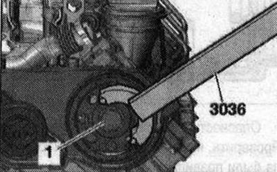
Remove the corresponding chain from the camshaft. Remove the upper part of the intake manifold. Remove the high-pressure pump toothed belt. Unscrew bolt "1" of the leading pulley of the toothed belt by about 2 turns, for this use the counter support "3036".

Remove the corresponding chain from the camshaft. Remove the upper part of the intake manifold.…


Remove the drive pulley of the toothed belt with the puller "T10320". Remove the left cylinder head cover.
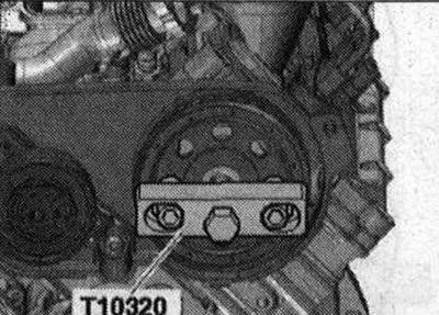
Remove the drive pulley of the toothed belt with the puller «T10320». Remove the left cylinder head…


Remove the EGR radiator changeover valve "N345" "pos. 1" from the bracket. Unscrew the bolt "4" and the pin with the ball head "2". Release the wiring harness "3" on the rear left coolant pipe. Ignore the "arrows".
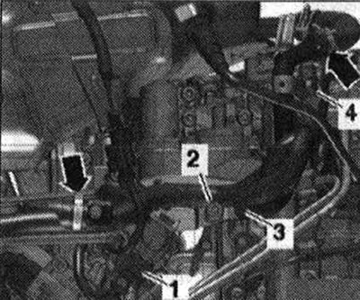
Remove the EGR radiator changeover valve «N345» «pos. 1» from the bracket. Unscrew the bolt «4» and…


Unscrew the union nut "1" of the high-pressure line. Unscrew the bolts "arrows" and remove the fuel rail from the left cylinder head.
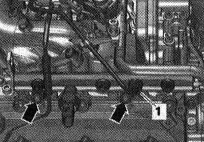


Unscrew the union nut «1» of the high-pressure line. Unscrew the bolts «arrows» and remove the fuel…


Loosen the bolts and nuts of the crankshaft frame in the sequence "18...1". When removing the camshafts, pay attention to the rocker arms and compensators. Carefully remove the crankshaft frame from the camshafts.
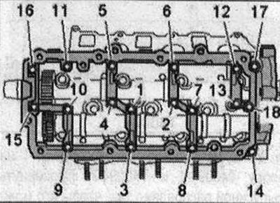
Loosen the bolts and nuts of the crankshaft frame in the sequence «18...1». When removing the…


Installation


Risk of damage to the thrust bearing in the crankshaft frame. Install the camshafts strictly according to the description using the camshaft installation tool "T40094". Risk of contamination of the lubrication system. Close open parts of the cylinder head. Remove residual sealant from the cylinder head and camshaft frame, for example, using a rotating brush attachment with plastic bristles. Clean the mounting surfaces; there should be no oil or grease on them. Lubricate the working surface of the camshafts with oil. Equip the camshaft installation tool "T40094" as follows: insert the support "T40094/2" into the socket "A", insert the support "T40094/1" into the socket "D".
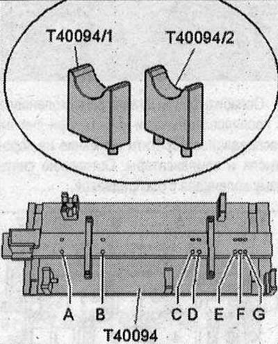


Risk of damage to the thrust bearing in the crankshaft frame. Install the camshafts strictly…


Install the exhaust camshaft "1" on the support "T40094/1" and "T40094/2". Turn the exhaust camshaft so that it can be locked with the lock in the "TDC" position "arrow". Install the camshaft installation tool "T40096" on the gear engagement of the exhaust camshaft so that each jaw of the clamping device engages on each half of the gear. Tighten the clamping device with a knurled wheel until the tooth profiles are at the same level.

Install the exhaust camshaft «1» on the support «T40094/1» and «T40094/2». Turn the exhaust…


Install the intake camshaft "2" in the camshaft installation tool "T40094". The locking pin "3" must enter the groove of the intake camshaft. Move the exhaust camshaft "1" toward the intake camshaft "arrows" so that the teeth engage.
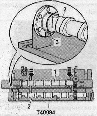
Install the intake camshaft «2» in the camshaft installation tool «T40094». The locking pin «3»…


Make sure that the camshafts are positioned correctly: the "arrow" recesses on both camshafts must be facing outward.
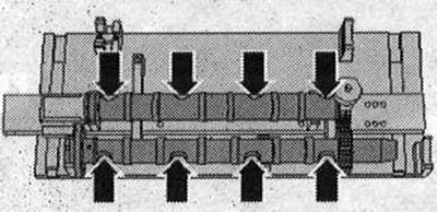


Make sure that the camshafts are positioned correctly: the «arrow» recesses on both camshafts must…


Install the crankshaft frame "1" on both camshafts. All camshaft bearings must be on the camshafts. Install the camshaft installation tool "T40095" on the camshafts by aligning the gripping pliers and securing with the notched nuts "2". Apply tension to the camshafts by tightening the notched nuts "3" upwards.
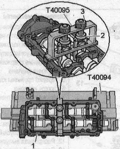
Install the crankshaft frame «1» on both camshafts. All camshaft bearings must be on the camshafts.…


Make sure there are "arrow" pins in the cylinder head. If there are no centering pins, insert them.
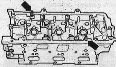
Make sure there are «arrow» pins in the cylinder head. If there are no centering pins, insert them.


Consider the expiration date of the sealant. Cut off the tube tip along the front mark (diameter hole approx. 1.5 mm). For better presentation, the crankshaft frame is shown without camshafts. Turn the crankshaft frame over. Risk of clogging the lubrication system channels with excess sealant. The sealant beads must not: be thicker than the prescribed size. Apply a bead of sealant "arrows" to the clean mounting surfaces of the camshaft frame, as shown in the figure. The grooves of the mounting surfaces must be filled with sealant. The sealant beads must protrude above the mounting surface by 1.5... 2.0 mm. Install the crankshaft frame within 5 minutes after applying the sealant.
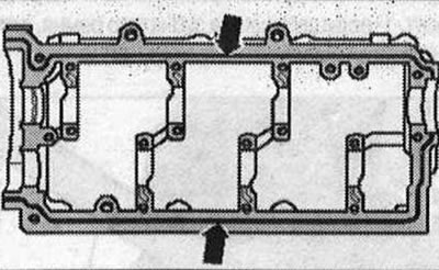


Consider the expiration date of the sealant. Cut off the tube tip along the front mark (diameter…


Risk of engine damage. Check that all roller rocker arms are correctly positioned on the ends of the valve stems and the compensators. Fit the crankshaft frame with both camshafts and the camshaft installation tool "T40095" to the cylinder head. Tighten the crankshaft frame bolts. Remove the camshaft installation tool "T40095" and "T40096". After fitting the crankshaft frame, allow the sealant to harden for approx. 30 min. Refit in reverse order. Fit the left cylinder head cover. Replace the camshaft oil seal. Fit the injection pump toothed belt and the upper section of the intake manifold. Fit the camshaft drive chains. Risk of damage to the valves and piston crowns after working on the valve mechanism. Since the hydraulic compensators must be settled, do not start the engine for approx. 30 min. after fitting the camshafts. To ensure that no valve comes into contact with the cylinder head during operation, carefully turn the engine at least 2 revolutions.
The article was checked by auto expert Timur Bazhenov
This article is available at russian, bulgarian, belarusian, ukrainian, serbian, croatian, romanian, polish, slovak, hungarian

Share information:
Previous articles
Audi Q Q5 Type 8R: Diesel engine 3.0 l
Next articles

Valve mechanism
Removal the cylinder head
Cylinder head
Removal the right cylinder head cover
Removal camshafts — right cylinder head
Oil pump and lower part of oil pan
Removal the oil pump
Upper part of the oil pan


Similar articles on other Audi car models:
Cylinder head — removal and installation Audi 80 B3 (1986-1991, petrol)
Cylinder head — removal, inspection and installation Audi 100 C3 (1982-1990, diesel)
Removal and installation the cylinder head (petrol) Audi A3 Type 8L (1996-2003)
Cylinder head gasket faults Audi A4 B5 (1994-2001, petrol)
Cylinder head — 1.8-I engine (125/150 hp) Audi A6 C5 (1997-2004)
Left cylinder head cover Audi A8 D2 (1994-2002)
Cylinder head — design description Audi A2 (1999-2005)
Link to this page in different formats


Visitor comments

No comments yet


How much will 13 + 44 =


Q7 4L(2005-2015, diesel) 
  • General information
  • Operating instructions
  • Maintenance
  • Power unit
  • Diesels 3.0 l (BUG, BUN, CAS)
  • Diesels 3.0 l (CATA, CCMA)
  • Diesels 3.0 l (CJGA/CJGC)
  • Diesels 4.2 l (BTR, CCFA/CCFC)
  • Cooling system
  • Fuel and exhaust system
  • Engine management system
  • Starting and charging
  • Transmission
  • Automatic gearbox
  • Drive shafts
  • Chassis
  • Brake system
  • Front suspension
  • Rear suspension
  • Steering system
  • Body
  • Air conditioner
  • Exterior
  • Interior
  • Electrical equipment
  • Equipment and devices
  • Electrical circuits
 
Q5 8R(2008-2017) 
  • General information
  • User manual
  • Power unit
  • Petrol engine 2.0 l
  • Petrol engine 3.2 l
  • Fuel system (petrol)
  • Diesel 2.0 liter (CA)
  • Diesel 2.0 liter (CG/CJ/CM)
  • Diesel engine 3.0 l
  • Fuel system (diesel)
  • Transmission
  • Manual gearbox 0B1
  • Manual gearbox 0B2
  • Automatic gearbox 0B5
  • Automatic gearbox 0B6
  • Chassis
  • Front suspension
  • Rear suspension
  • Brake system
  • Steering
  • Body
  • Exterior
  • Interior
  • Doors, locks and windows
  • Safety system
  • Ventilation and heating
  • Electrical equipment
  • Power devices
  • Equipment and devices
  • Lighting and alarm
  • Audio system
  • Electrical circuits
 
AudiManual.ru © 2017-2026 · Mobile version · Feedback · Sitemap: EN BG BY UA RS HR RO PL SK HU · Site search · News and articles
80 B2 · 80 B3 petrol · 80 B3 · 80 B4 · 100 C3 diesel · 100 C3 petrol · 100 C3 · 100 C4 petrol · 100 C4 · A3 Type 8L · A4 B5 petrol · A4 B5 · A4 B6 petrol · A4 B6 · A4 B7 · A4 B8 · A6 C4 · A6 C5 · A6 C5 Allroad · A8 D2 · Q5 Type 8R · Q7 Typ 4L · Audi A2 ·
This site uses cookies 🍪. Click the button to accept this fact.