
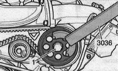
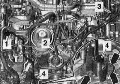
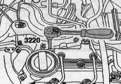
Left cylinder head: Remove the high-pressure pump toothed belt and the toothed belt tension roller. Unscrew bolt "1" of the toothed belt drive pulley by about 2 turns, for this use counter support "3036".
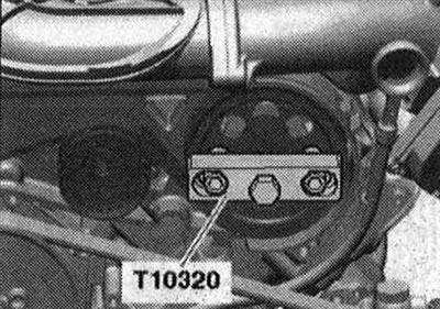
Remove the drive pulley of the toothed belt using the puller "T10320".
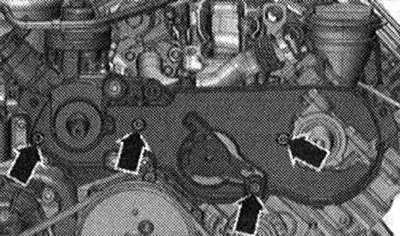
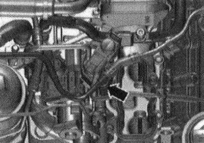
Unscrew the "arrow" bolts, leave the rear cover of the toothed belt in the mounting position.
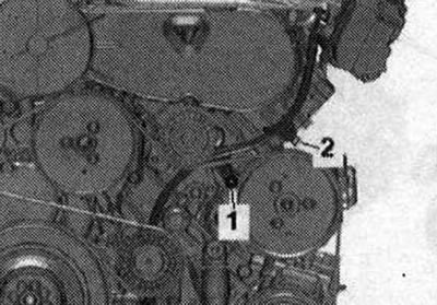
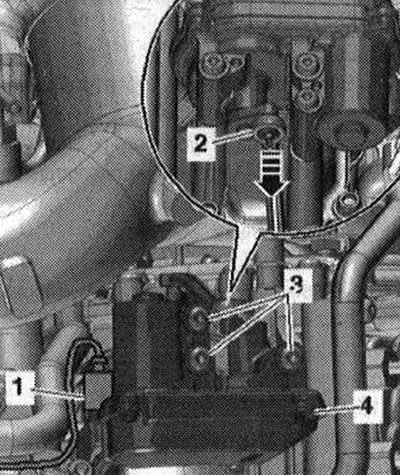
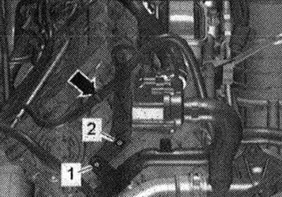
Loosen the bolt "2" of the oil dipstick guide tube. Ignore "Pos. 1".
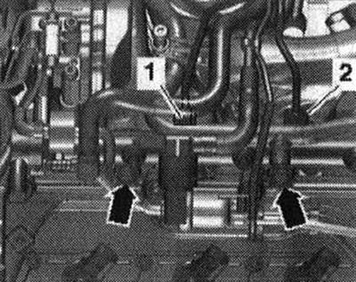
Unscrew union nuts "2" and "3", release and remove the high-pressure line. "Pos. 1,4" and "arrows" do not take into account.
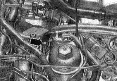
Remove the tee from the coolant hose "arrow".
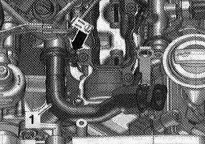
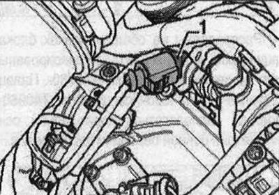
Disconnect plug connector "1" of intake manifold flap drive motor 2 "V275" "pos. 4". "Pos. 2,3" and "arrow" do not count.
Loosen the clamp "arrow" and the EGR tube "1".
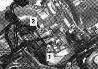
Right cylinder head: Remove the right intermediate pipe. Remove the coolant pipe on the right at the top. Unscrew the bolts "arrows" and remove the protective screen of the high-pressure line. Unscrew the union nuts "1" and "4", release and remove the high-pressure line. Ignore "Pos. 2,3". Unscrew the bolts "1" and "2" of the eye for hanging the engine and the pump of the radiator of the exhaust gas recirculation system "V400". Release the wiring harness with a lever "80 - 200" "arrow".
Disconnect the coolant line "arrow". Disconnect the glow plug connectors of cylinders 2 and 3.
Disconnect plug connector "1" of the intake manifold flap motor "V157". Ignore the "arrows".
Disconnect plug connector "1" (black) of exhaust gas temperature sensor 1 "G235". Remove plug connector "2" (orange) of temperature sensor in the exhaust gas recirculation system "G98" from the bracket and disconnect the connector.
Place a rag under the disconnection point to collect any leaking fuel. Disconnect the supply "1" and return "2" fuel lines. Unscrew the "arrow" bolts and set aside the fuel rail with the connected fuel hoses. Ignore "Pos. 1, 2".
All
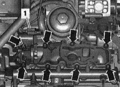
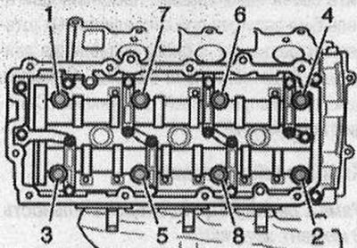
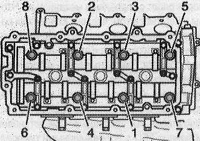
Loosen the cylinder head bolts in the sequence "1...8". Unscrew the bolts and carefully remove the cylinder head. Risk of damaging the glow plug rods when installing the cylinder head. It is prohibited to place the removed cylinder head with the glow plugs installed on the mating surface, since the glow plug rods slightly protrude beyond the mating surface.
Installation
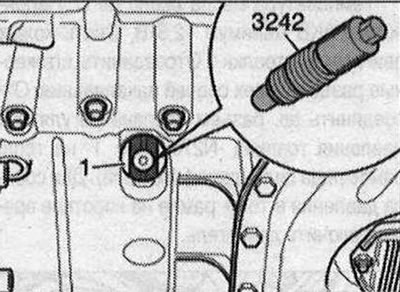
Install in reverse order. Risk of damaging the sealing surface. Carefully remove any sealant residue from the cylinder head and cylinder block. Avoid the formation of long scratches or scoring. Risk of damaging the cylinder block. There must be no oil or coolant in the blind holes of the cylinder head fastening bolts. Risk of cylinder head gasket leakage. Carefully remove any sealant residue from the cylinder head and cylinder block during repairs. Avoid the formation of long scratches or scoring. Carefully remove any residue after sanding and grinding. Remove the new cylinder head gasket from its packaging immediately before installation. Handle the gasket with particular care to prevent damage to the silicone layer and the grooves of the cylinder head gasket. Risk of damaging open valves. When installing an exchange cylinder head, remove the plastic base to protect against closed valves only if it comes into direct contact with the cylinder head. Risk of damaging the valves and piston crowns after working on the valve mechanism. To ensure that no valve comes into contact with the cylinder head during operation, carefully turn the engine at least 2 turns. Replace bolts that were tightened with additional tightening. Replace self-locking nuts, lip seals, gaskets and O-rings. Modification of the cylinder head of TDI engines is prohibited. When installing an exchange cylinder head with installed camshafts, lubricate the contact surfaces between the hydraulic lifters, rocker arms and the working surfaces of the cams with oil. Hose nipples, air ducts and hoses must be cleaned of oil and grease before installation. Secure all hose connections with hose clamps of the appropriate series. To ensure reliable fastening of the air duct hoses on the nipples, treat the threaded connections of the already used clamps with a rust remover. If the cylinder head or cylinder head gasket was replaced, the coolant and oil must be replaced. Before installing the cylinder head, set the crankshaft and camshafts to "TDC": Fixing bolt "3242" must be screwed in the "TDC" position of crankshaft "1".
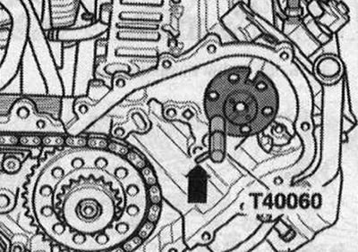
The camshafts on both cylinder heads must be fixed with the adjusting font "T40060". The "arrow" pin in the "T40060" installation pin must be located parallel to the axis of symmetry of the camshaft chain transmission.
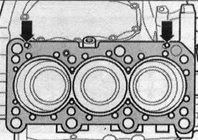
Take into account the markings on the cylinder head gasket
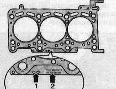
- 1. Holes
- 2. Part number
Note: After replacing the cylinder head gasket or cylinder head, select a new cylinder head gasket according to the number of holes in the old gasket. If the crank mechanism parts have been replaced, the new cylinder head gasket should be selected according to the measurements of the piston protrusion at the "TDC" position. The left and right cylinder head gaskets cannot be mixed up, they have different shapes.
Clean the sealing surfaces from oil and grease. Observe the expiration date of the sealant. Cut off the tube tip at the front mark (hole diameter approx. 5mm). The bolted connection of the parts must be closed 15 minutes after applying the sealant.
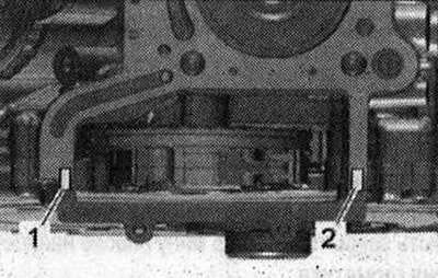
Left Cylinder Head: Apply sealant beads "1" and "2" to the clean seating surface of the cylinder block and lower timing chain cover as shown in the figure.
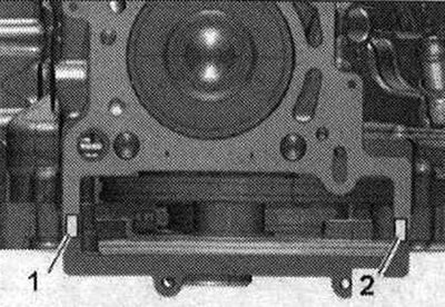
The sealant is applied in the specified quantity.
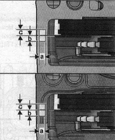
a = 7mm, b = 7mm, c = 7mm.
Apply the cylinder head gasket. Apply beads of sealant "1" and "2" to the cylinder head gasket as shown in the figure.
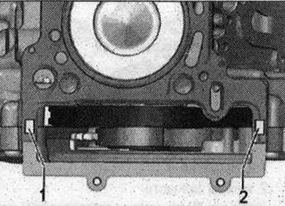
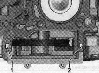
Right Cylinder Head: Apply sealant beads "1" and "2" to the clean seating surface of the cylinder block and lower timing chain cover as shown in the figure.
The sealant is applied in the specified quantity.
a = 7mm, b = 7mm, c = 7mm.
Install the cylinder head gasket. Apply a strip of sealant "1" and "2" to the recesses of the cylinder head gasket.
All
Pay attention to the centering bushings "arrows" in the cylinder block. Mounting position of the cylinder head seal: marked "top" or the part number for the cylinder head. Install the cylinder head.
Tighten the cylinder head bolts. Do not tighten the cylinder head bolts further.
Left cylinder head: Install the EGR pipe. Install the dipstick guide pipe. Remove the timing belt tensioner roller and the high-pressure pump timing belt.
Right cylinder head: Install the coolant pipe on the right top. Install the right intermediate pipe.
All
Install high-pressure fuel lines. Install cylinder head cover. Install upper intake manifold. Install camshaft drive chains. Change oil. Change coolant. Check fuel system for leaks.
Compression check
Oil temperature is about 80°C. Battery voltage is at least 12.5 V. Remove the engine casing "arrows". Disconnect the plug connectors of all glow plugs. Disconnect the electrical connector of the fuel pressure regulator valve "N₂76" "pos. 1" on the fuel rail of cylinder bank 1 (right). To relieve pressure in the fuel rail, briefly start the engine.
Remove all glow plugs.
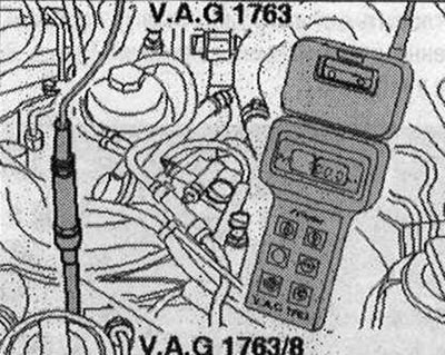
Screw the adapter into place of the glow plugs "V.A.G 1763/8" and connect the compression gauge "V.A.G 1763".
The second mechanic should turn the engine crankshaft with the starter until the pressure on the compression gauge stops increasing. Check each cylinder.
| Compression values | Bar excess pressure |
| New | 28...33 |
| Wear limit | 21 |
| Maximum difference between cylinders |
Installation
Installation is carried out in reverse order, observing the following: Install glow plugs. Since the engine was started with the plug connectors disconnected, the error "Query fault memory" in the "Vehicle self-diagnosis" function was stored in the engine control unit.
(Text provided by the online resource: «AUDIMANUAL»)