
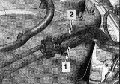
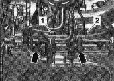
Unscrew union nuts -1- and -2-. Unscrew bolts -arrows- and set aside. ramp with connected fuel hoses.
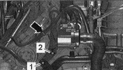
Release wiring harness -arrow- using lever -80 - 200-. -Pos. 1,2 - do not take into account.
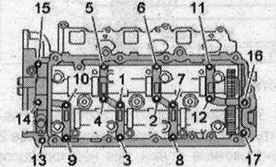
Loosen the crankshaft frame bolts and nuts in the sequence -17...1-. When removing camshafts, pay attention to the rocker arms and compensators.
Carefully remove the crankshaft frame from the camshafts.
Installation
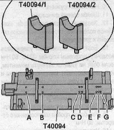
Replace the front right cylinder head cover. Risk of damage to the thrust bearing in the crankshaft frame. Install the camshafts strictly in accordance with the description using the camshaft installation tool -T40094-. Risk of contamination of the lubrication system. Close open cylinder head parts. Remove remaining sealant from the cylinder head and camshaft frame, for example using a rotating brush with plastic bristles. Clean the seating surfaces; There should be no oil or grease on them. Lubricate the working surface of the camshafts with oil. Equip the camshaft installation tool -T40094- as follows: insert the support -T40094/2- into the seat -B-, insert the support -T40094/1 - into the seat -C-.
Place exhaust camshaft -1- on support -T40094/1- and -T40094/2-. Rotate the exhaust camshaft until it can be locked in position "TDC" -arrow-.
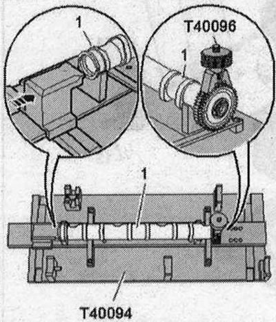
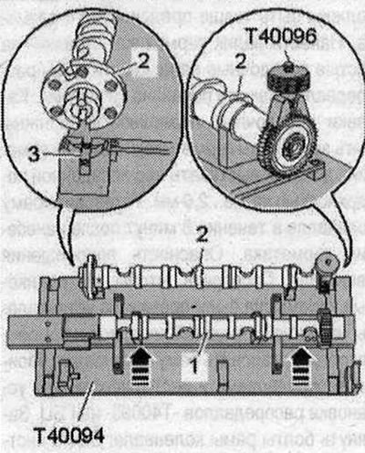
Install the intake camshaft -2- into the camshaft installation tool -T40094-. The retaining bridge -3- must fit into the groove of the intake camshaft. Position the camshaft tool -T40096- on the intake camshaft teeth so that each elbow of the clamping device fits into the corresponding gear half. Tighten the clamping device using the knurled wheel until the tooth profiles are level. Push the exhaust camshaft -1- towards the intake camshaft -arrows- until the teeth engage.
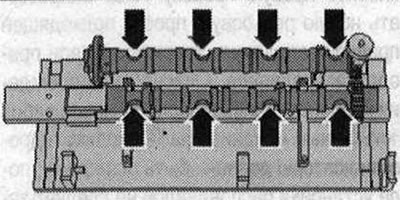
Make sure that the camshafts are in the correct position: the recesses -arrows- on both camshafts must point outwards.
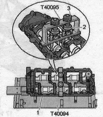
Place crankshaft frame -1- on both camshafts. All camshaft bearings must be on the camshafts. Place the camshaft setting tool -T40095- on the camshafts; to do this, align the gripping pliers and secure with knurled nuts -2-. Apply tension to the camshafts by tightening the knurled nuts -3- upwards.
Make sure that the pins -arrows- are present in the cylinder head. If there are no centering pins, insert them. Consider the expiration date of the sealant. Cut off the tube spout at the front mark (hole diameter approx. 1.5 mm). For better illustration, the crankshaft frame is shown without camshafts. Turn over the crankshaft frame. There is a danger of clogging the lubrication system channels if there is excess sealant. The sealant beads must not be thicker than the prescribed size. Apply a bead of sealant -arrows- to the clean seating surfaces of the camshaft frame as shown in the illustration. The grooves of the seating surfaces must be filled with sealant. The sealant beads should protrude 1.5...2.0 mm above the seating surface. Install the crankshaft frame within 5 minutes after applying the sealant. Risk of engine damage. Check that all roller rocker arms are correctly installed on the ends of the valve stems and compensators. Install the crankshaft frame with both camshafts and the camshaft installation tool -T40095- onto the cylinder head. Tighten the crankshaft frame bolts. Remove camshaft installation tool -T40095- and -T40096-. After installing the crankshaft frame, allow the sealant to cure for about 30 minutes. Install in reverse order. Install the right cylinder head cover. Press the new screw plug flush with a suitable mandrel. Install the camshaft drive chains. Risk of damage to valves and piston crowns after working on the valve mechanism. Since the hydraulic lifters must be seated, after installing the camshafts, the engine should not be started for approx. 30 min.
To ensure that no valve comes into contact with the cylinder head during operation, carefully turn the engine at least 2 turns.
Visitor comments