
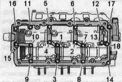
Tighten the bolts and nuts in 2 stages in the sequence shown
| Stage | Bolts/nuts | Tightening torque |
| 1 | "1...8" | Screw in by hand until it stops. The bearing frame should fit against the cylinder head over the entire contact surface |
| 2 | "1...18" | 9 Nm |
Frame to right cylinder head - sequence and tightening torque
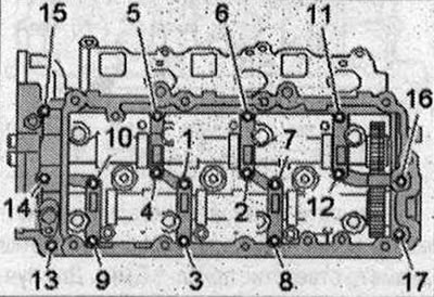
Tighten the bolts and nuts in 2 stages in the sequence shown.
| Stage | Bolts/nuts | Tightening torque |
| 1 | "1...17" | Screw in by hand until it stops. The bearing frame should fit against the cylinder head over the entire contact surface |
| 2 | "1...17" | 9 Nm |
The figure shows the cylinder head of the 2nd row of cylinders (left).
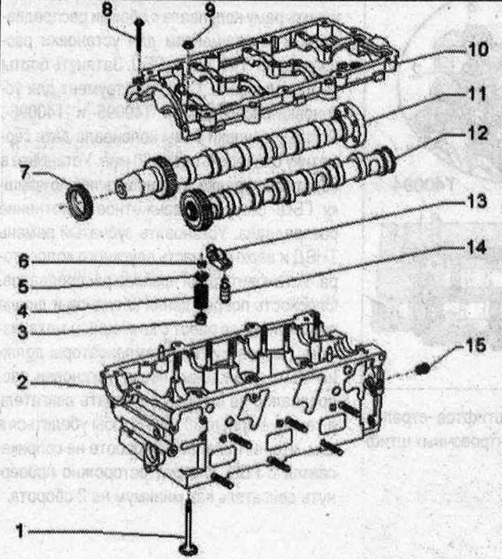
Valve mechanism
1. Valve: cannot be processed, only lapping is allowed; mark the mounting position for reinstallation; check; 2. Cylinder head: Due to tight tolerances, machining of valve seats is not permitted; 3. Valve stem seal; 4. Valve spring; 5. Valve spring plate; 6. Valve cracker; 7. Camshaft oil seal: replace; 8. Bolt; 9. Nut; 10. Camshaft frame: with integrated camshaft bearings; 11. Intake camshaft: maximum runout: 0.01 mm; 12. Exhaust camshaft: maximum runout: 0.01 mm; 13. Roller lever: Mark the mounting position for reinstallation; check the roller bearings for ease of rotation; lubricate working surfaces before installation; 14. Hydraulic compensator: mark the mounting position for reinstallation; check; lubricate working surfaces before installation; 15. Pressure limiting valve 1.0 bar: for lubrication points in the cylinder head; 25 Nm
The article is a reprint of material from: audimanual