
Table of contents: Removal the diesel particulate filter ↓ Installation ↓
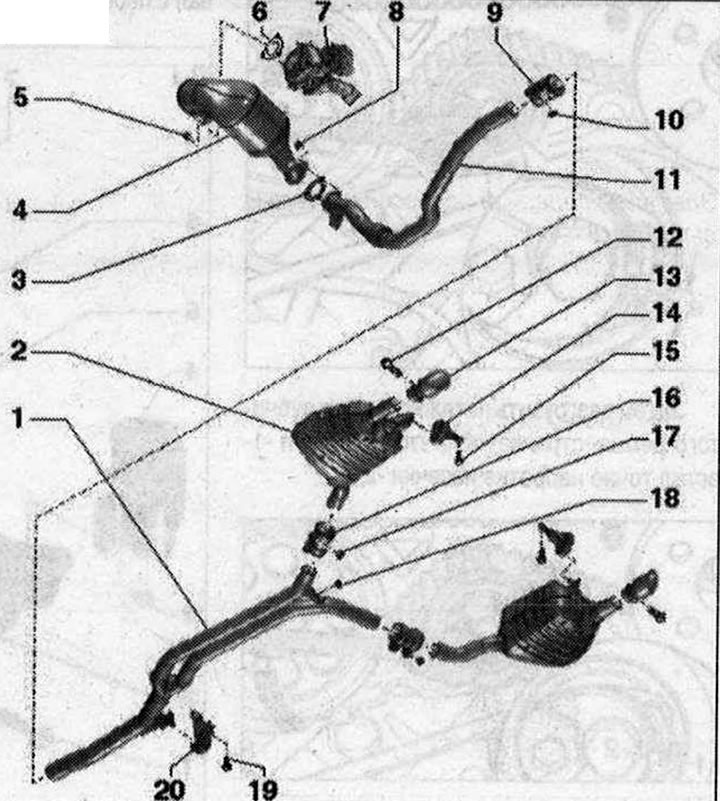
Muffler 1. Y-pipe: installed at the factory as one piece with the rear mufflers, in case of repair it is replaced separately; the cut between the tee and the rear muffler; align the exhaust system without mechanical stress; 2. Additional muffler: factory complete with unit with tee and muffler outlet pipe; in case of repair of the tee, the additional muffler and exhaust pipe are replaced separately; align the exhaust system without mechanical stress; 3. Gasket: replace; 4. Diesel particulate filter: with catalyst; with pressure line of exhaust gas pressure sensor 1 "G450"; after replacement, perform "adaptation" through "Guided functions"; 5. Nut: replace; lubricate with heat-resistant paste; 23 Nm; 6. Gasket: replace; 7. Turbocharger; 8. Nut: replace; 23 Nm; 9. Double clamp, front: Before tightening, align the exhaust system without mechanical stress; tighten the connections evenly; 10/17. Nut: 23 Nm; 11. Intake pipe: with detachable element; the detachable element must not be bent more than 10° - risk of damage; protect from impacts and shocks; align the exhaust system with the cut area freely; 12/14. Bolt: 23 Nm; 13. Exhaust pipe: factory installed with main muffler as 1 piece; replace separately during repair; 15. Suspension mount: replace if damaged; check pre-tension; 16. Rear clamp: for replacing the main muffler tee individually; before tightening, align the exhaust system without mechanical stress; tighten the connections evenly; 18. Nut: replace; 23 Nm; 19. Bolt; 20. Suspension mount: replace if damaged; check pre-tension
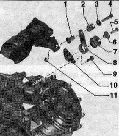
Components of the downpipe suspension 1/6. Spacer sleeve; 2. Pressure spring; 3. Washer 4/5/9. Bolt, 23 Nm; 7. Buffer; 8. Overlay; 10. Bracket; 11. Nut
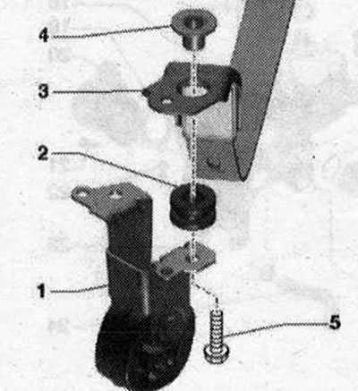
Front suspension elements of the exhaust system 1. Hanging mount; 2. Buffer; 3. Tightening clamp; 4. Spacer sleeve; 5. Bolt, 20 Nm
Removal the diesel particulate filter
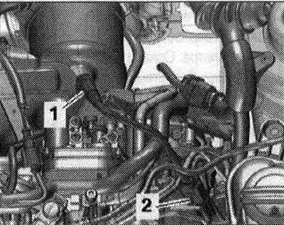
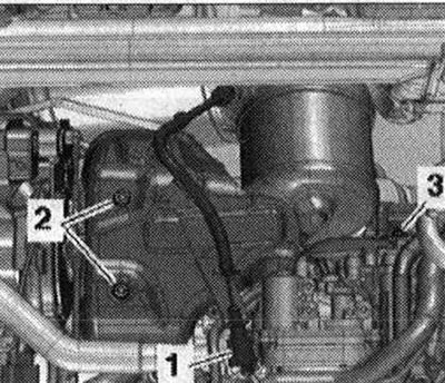
Remove the brace. Remove the front wall of the water drainage box. Remove the exhaust pipe. Remove connector "2" from the bracket and disconnect it. Ignore "Pos. 1".
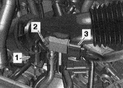
Release and disconnect plug connector "1" of exhaust gas temperature sensor 3 "G495". Unscrew bolts "2" and "3". Remove the turbocharger heat shield.
Disconnect the plug connectors.
- 1. For exhaust gas temperature sensor 4 "G648"
- 3. For pressure sensor 1 for exhaust gas "G450"
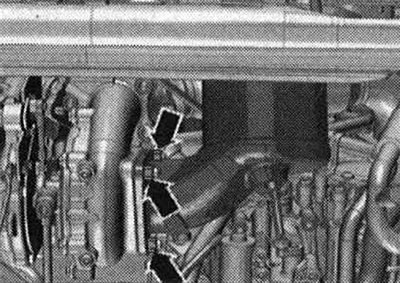
Unscrew bolt "2" and remove pressure sensor 1 EG "G450". Unscrew nuts "arrows" and remove the particulate filter.
Installation
Installation in reverse order. Replace the gaskets and self-locking nuts. When installing, all cable ties must be placed in their original places. Install the turbocharger heat shield. Install the exhaust pipe. Install the front wall of the water drain box. Install the brace. After replacing the particulate filter, perform the "Adaptation" function in the "Guided functions" mode.
[Read the original source on the website audimanual]