
Table of contents: Important instructions for… ↓ If a used injector is reinstalled ↓ Removal air from the fuel system and… ↓
Instructions: The following shows the removal and installation of the injectors on the left bank of cylinders 2. Stage of work only on cylinder bank 1: remove the upper part of the air filter housing together with the air flow meter. On cylinder bank 2, it is necessary to unscrew the coolant expansion tank, the coolant lines remain connected.
Remove the engine casing. Mark the mutual belonging of the injectors to the cylinder. Reinstallation is permitted only on the same cylinder. Observe the rules of cleanliness when working with the injection system. Immediately close the open nipples with a suitable cap. Remove the nipples of the return lines on the injectors, to do this, press both plates down and simultaneously pull the middle part up to unlock "arrow".
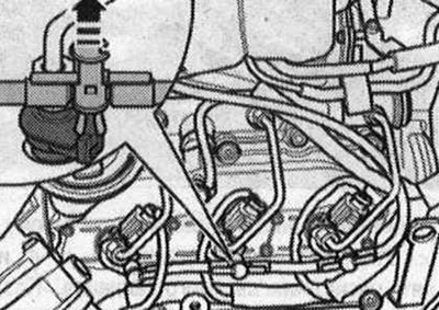
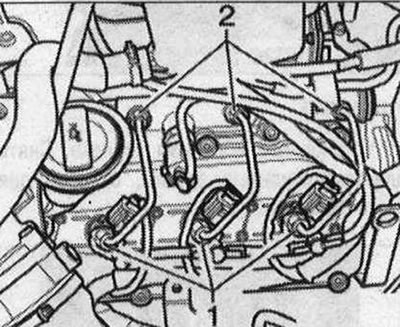
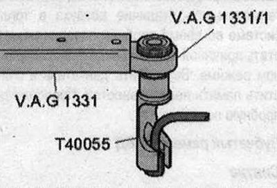
Disconnect the plug connectors on the injectors to be removed. Loosen the union nuts of the high-pressure lines "1" using the insert "T40055" SW 17 on the injection modules. Loosen the union nuts of the high-pressure lines "2" using the wrench SW17 "V.A.G 1331/6" on the ramp element.
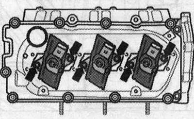
Unscrew the covers of the "arrow" injectors. Pull the covers up and turn them 90°.
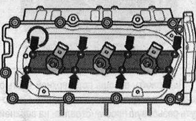
Loosen the clamping brackets of the "arrow" injectors.
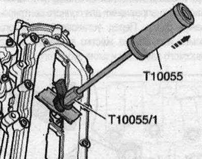
Remove the injectors using the "T10055" puller with the "T10055/1" adapter. Place the removed injectors on a clean cloth.
Important instructions for installing injectors
The following components and gaskets or sealing rings must be replaced each time they are removed or installed: "copper washer", "injector seat sealing ring", "injector return line sealing ring". The following parts and seals, as well as sealing rings, must be replaced each time the injector is replaced: "clamp", "copper washer", "injector seat sealing ring", "injector return line sealing ring". Lubricate all sealing rings with assembly fluid or oil before installation. When reusing high-pressure lines, observe the corresponding cylinder designation. High-pressure lines can be reused after the following checks. Check the sealing cone of the corresponding high-pressure line for deformations and cracks. The hole must not be deformed or damaged. Lines with corrosion must not be reused.
If a used injector is reinstalled
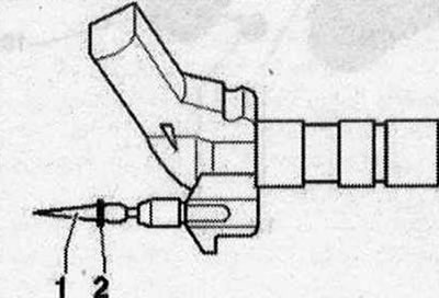
Treat the top of the nozzle with rust remover. After about 5 minutes, remove any rust or oil particles with a clean rag. If the nozzle is heavily soiled, additionally clean the top with a soft brass brush to facilitate removal of the copper seal (do not allow the brass brush to come into contact with the nozzle sprayer). To remove the old copper injector seal, carefully clamp it in a vice until it gets stuck between the clamping jaws when turning. Using light rotational movements of the hand, remove the injector from the copper seal. Use a scraper to clean off deposits under the copper seal. Use a plastic sleeve to install a new copper seal. To avoid damaging the sealing ring, fit the new ring "2" onto the return fuel line nipple using the mounting rod "1". To remove rust particles from the sealing surface of the injector, clean the injector seat in the cylinder head with a rag soaked in oil or rust remover. Do not damage the sealing surface.
Install the injectors. Tighten the union nuts of the high-pressure fuel lines by hand. Check the installation without stress. Use a torque wrench with a ratchet and a socket wrench attachment "T40055" to tighten the high-pressure lines on the injectors.
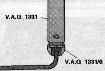
To tighten the high-pressure lines to the fuel rail, use a torque wrench with an installation tool SW 17 "V.A.G 1331/6". Observe the tightening torque.
Carefully install the return line fittings onto the injector through the sealing collar (pre-check the lip seal for damage). After the lock clicks into place, carefully press the release bracket down. After replacing one or more injectors, the "fuel quantity correction (IMA)" and "voltage correction (ISA)" for the new injectors must be entered into the engine control unit. Additionally, check all other injectors for "fuel quantity correction (IMA)" and "voltage correction (ISA)" and the correctness of the specified correction values. If the engine control unit has the correct correction values, do not re-enter them under any circumstances.
Removal air from the fuel system and checking it for leaks
To bleed air, do not open the high-pressure terminals; air will leave the fuel system on its own. Let the engine idle for a few minutes and then turn it off again. Switch off the ignition. Check the tightness of the entire fuel system and the terminals of the return lines (6 pieces). If there is a leak, despite the fact that the tightening torque has been observed, it is necessary to replace the corresponding unit. The return lines are replaced only in a set with a pressure-reducing valve. Perform a test drive of at least 20 km and, having performed at least one acceleration with maximum load, check the high-pressure area again for tightness. The presence of air in the fuel system during a test drive may cause the engine to operate in emergency mode. Switch off the engine and clear the fault memory. Continue the test drive.