
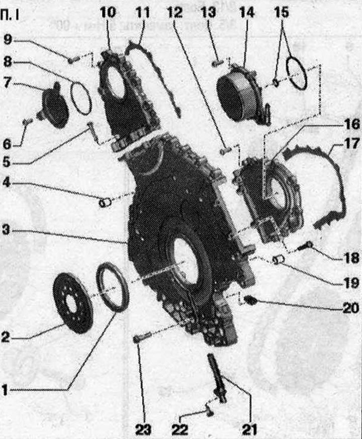
Timing chain lining installation diagram I 1. Crankshaft lip seal on the gearbox side; 2. Ring gear for engine speed sender -G28-; 3. Drive chain bottom cover; 4. Installation sleeve: 2 pcs.; 5/9/12. Bolt: replace; 6. Bolt: 9 Nm; 7. Cover; 8. Seal ring: replace; 10. Left drive chain cover; 11. Gasket: replace; 13/22/23. Bolt; 14. Vacuum pump; 15. Seal rings: replace; 16. Right drive chain cover; 17. Gasket: replace; 18. Bolt: replace; 19. Installation sleeve: 2 pcs.; 20. Seal: 2 pcs.; 21. Engine speed sender -G28-
Left drive chain cover - bolt sequence and torque
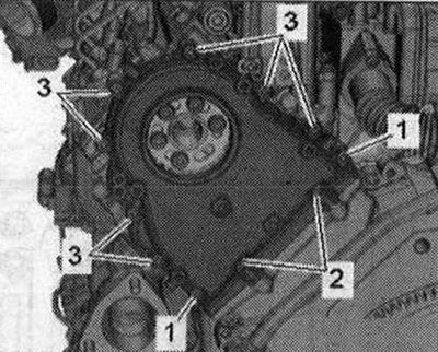
Tighten the bolts in 4 stages as follows
| Stage | Bolts | Tightening torque/turn angle |
| 1 | -1- | ZN-m |
| 2 | -2- | 9 Nm |
| 3 | -1- | 9 Nm |
| 4 | -3- | crisscross 9 Nm |
Right drive chain cover - bolt sequence and torque
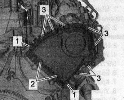
Tighten the bolts in 4 stages as follows.
| Stage | Bolts | Tightening torque/turn angle |
| -1- | 3 Nm | |
| 2 | -2- | 9 Nm |
| 3 | -1- | 9 Nm |
| 4 | -3- | crisscross 9 Nm |
Lower drive chain cover - bolt sequence and torque
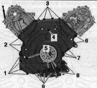
Tighten the bolts in 3 stages as follows.
| Stage | Bolts | Tightening torque/turn angle |
| 1 | -1...9- | 5 Nm from inside to outside crosswise |
| 2 | -1...7- | 9 Nm from inside to outside crosswise |
| 3 | -8,9- | 23 Nm |
Visitor comments