
Table of contents: Piston cooling oil nozzle ↓ Mounting position of pistons ↓ Mark the connecting rods ↓ Mounting position of connecting rods ↓
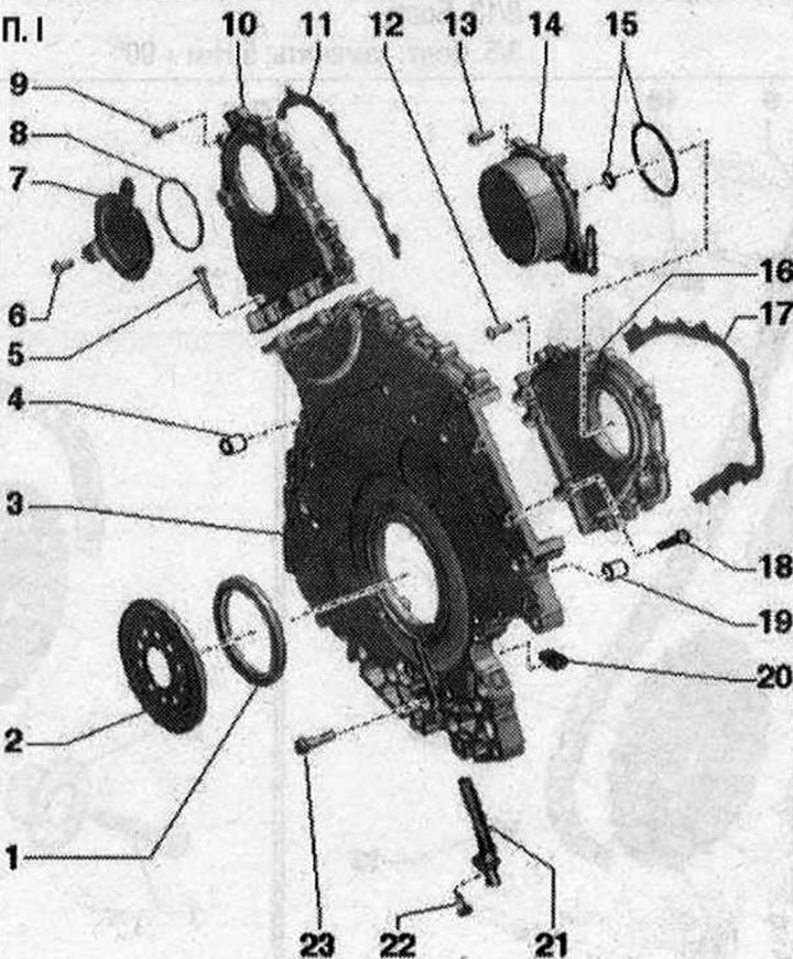
Pistons and connecting rods 1. Bolts: replace; lubricate the threads and mating surface with oil; 35 Nm + 90°; 2. Connecting rod cap: mark for reassembly; mark the cylinder with a colored pencil "B"; installation position: observe the cast marks "A"; 3. Bearing shells: install in proper position; mark previously used liners, but not on the working surface; replace bearing shells worn down to their original material; 4. Connecting rod: replace only the entire set; mark the cylinder with a colored pencil "B"; installation position: observe the cast marks "A"; axial clearance for each new connecting rod pair: 0.20...0.44 mm; 5. Retaining ring: replace; 6. Piston pin: if the pin is difficult to install, heat the piston to 60°C; remove and install using the "VW 222 A" mandrel; 7. Piston: Mark the installation position and the cylinder assignment; if a scratch forms on the piston bottom or on the piston skirt, replace the piston; check; install using a piston ring clamp; measure the inner diameter of the cylinder; check the piston protrusion at "TDC"; 8. Piston rings: place locks with 120° offset; remove and install using piston ring pliers; the "TOP" mark faces the piston bottom; measure thermal clearance
Piston cooling oil nozzle
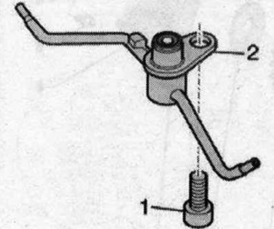
- 1. Bolt, 9 Nm
- 2. Oil nozzle for piston cooling with nozzle valve
Note: Do not bend the oil spray nozzles. Bent oil spray nozzles must be replaced.
Mounting position of pistons
Caution! Risk of damage to the piston bottom coating. To ensure correct subsequent installation of used pistons, mark the piston to cylinder with paint. Do not make notches on the piston bottom with a center punch or similar tools.
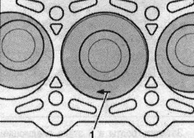
Installation position: arrow "pos. 1" on the piston bottom points towards the belt pulleys.
Mark the connecting rods
Mark the connecting rods and connecting rod lower head caps with paint for reassembly to indicate their correspondence to each other and to the cylinder "arrow". Replace the connecting rod only as an assembly. Do not mix up the connecting rod bearings.
Mounting position of connecting rods
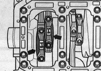
Mounting position: The larger shoulder of the connecting rods "arrows" faces the adjacent main bearing. The figure shows the front connecting rod pair.
(The original article is posted on the resource: «audimanual.ru»)