
Note: The engine is removed downwards along with the gearbox and subframe. For disposal or reuse, coolant should be drained into a clean container. When reassembling, install all binders in the places where they were originally installed. There is a danger of the vehicle tipping over when the engine is removed. Protect the vehicle; to do this, the luggage compartment must be empty. Risk of damage to electronic components when disconnecting the battery terminals. Follow the instructions when disconnecting the battery terminals.
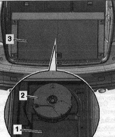
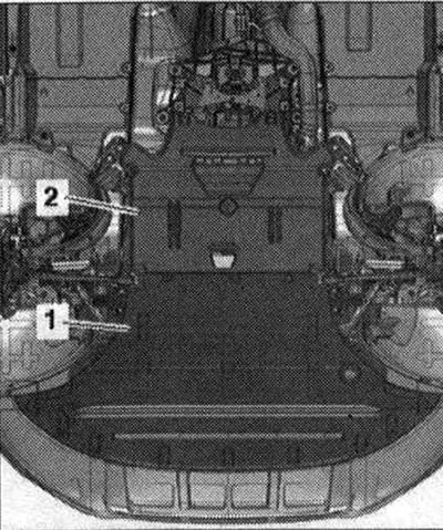
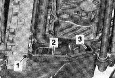
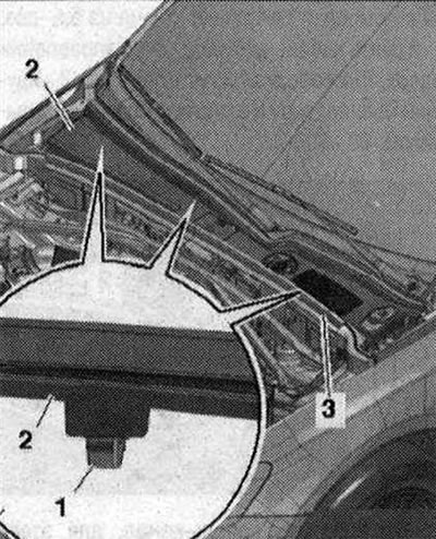
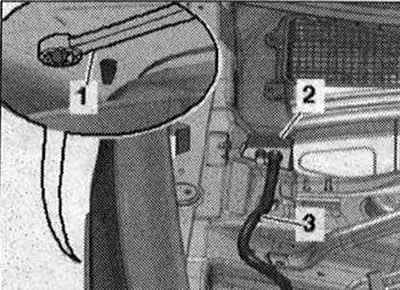
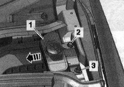
Move the front wheels to a straight ahead position. To rotate the driveshaft for removal, the electromechanical parking brake must be released before disconnecting the battery. Turn off the ignition. Remove trunk tray -3-. If equipped, remove Bassbox -2-. Unscrew the floor mat -1- above the cover.
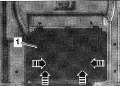
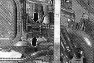
Unlock fastenings -arrows- and install cover -1-.
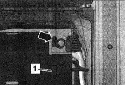
Remove the cover -1- over the negative terminal of the battery. Disconnect earth cable -arrow- from battery terminal. Empty the air conditioning circuit. Drain the power steering hydraulic oil using an oil drain tool from the reservoir.
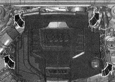
Remove engine cover -arrows-. Open the extension cover. tank.
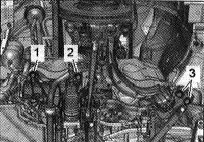
Remove the front wheels: right and left. Remove the front right and left fender liner. Remove noise insulation panels -1- and -2-.
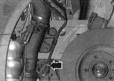
Place service tap tray -VAS 6208- under the engine. Unscrew the drain plug -arrow- on the connecting piece and drain the coolant. Remove the connecting fitting from the radiator by unclamping the bracket.
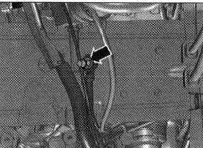
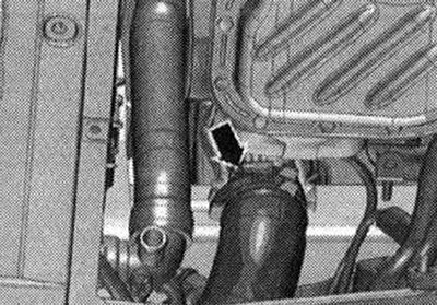
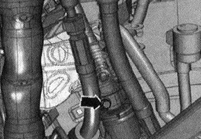
Remove the coolant hose from the left coolant pipe by loosening the hose clamp -arrow- and drain the coolant.
Disconnect the coolant hose from the radiator by pressing out the clamp -arrow- and drain the coolant.
Install a device for pumping out and collecting oil under the disconnection point. Disconnect oil return line -arrow- from power steering.
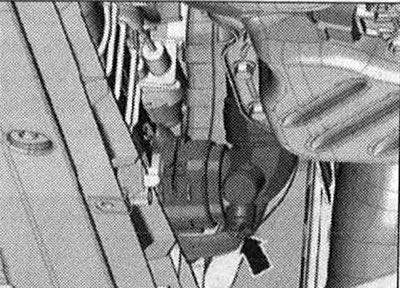
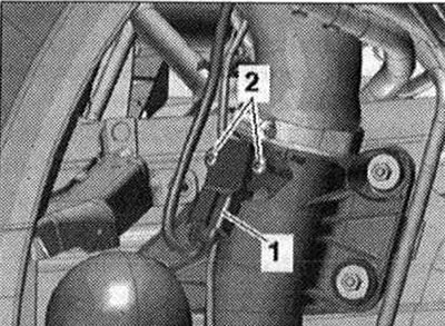
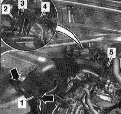
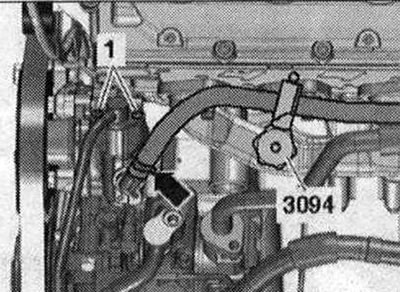
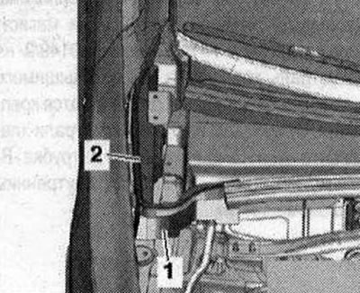
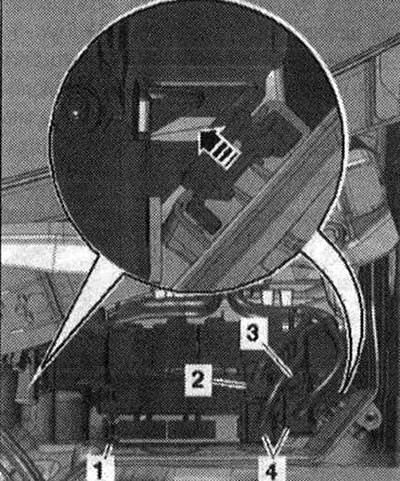
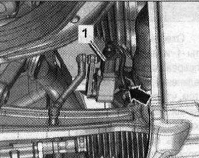
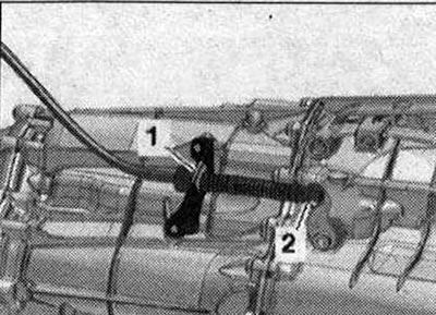
Disconnect electrical connector -1- from charge pressure sensor -G31- and free connector. -Pos. 2- do not take into account.
Unscrew the nut -arrow- on the right side member and release the ground cables.
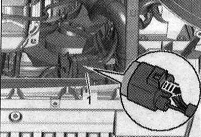
Disconnect the electrical connector -1- of the radiator fan, push the locking pin backwards -arrow- and press the lock downwards. Release the wiring harness from the mountings on the side member.
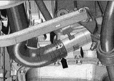
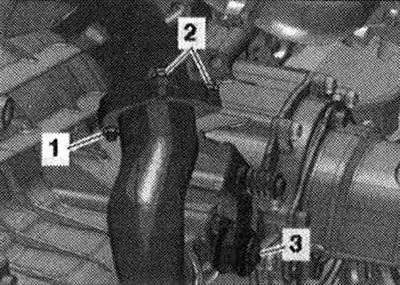
Remove the air inlet hose from the air inlet pipe and place the hose to one side by unclamping the clamp -arrow-.
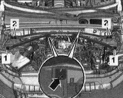
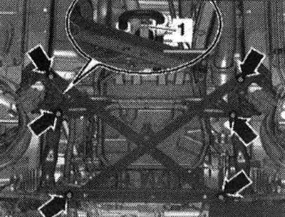
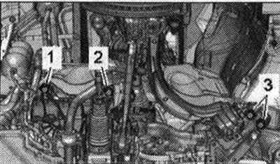
Unscrew the bolts -1- and nuts -3- on the left and right and remove the cross member of the radiator frame -2-.
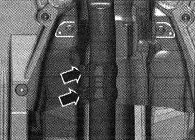
Install a device for pumping out and collecting used oil under the disconnection point. Disconnect ATF lines -arrows- at the disconnect points on the right side of the engine.
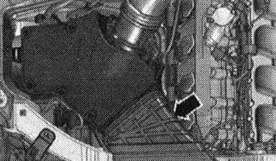
Remove air duct -arrow-.
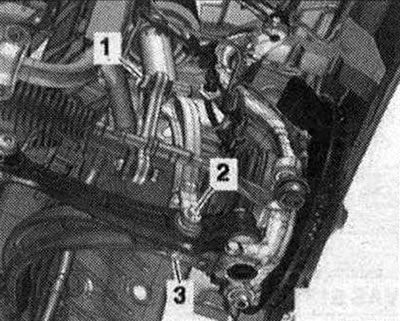
Disconnect electrical connector -1 for air mass meter -G70-. Unscrew bolt -3 and release exhaust gas pressure sensor 1 -G450--pos. 4- on the air duct pipe. Unplug and unplug connector -2-exhaust temperature sender 4 -G648- on air duct pipe. Remove the air hose with air mass meter -G70- by unclamping the hose clamp -5- and loosening the fasteners -arrows-.
Unscrew the bolts -1- and nuts -3- on the left and right and remove the cross member of the radiator frame -2-.
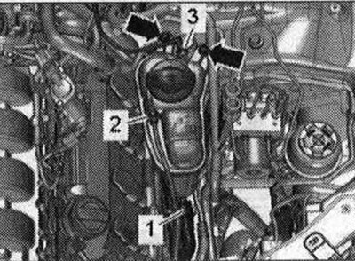
Disconnect vacuum line -1-. Remove the air housing. filter and disconnect the plug connector -2 of the air bypass valve on the reverse side. filter -N275-.
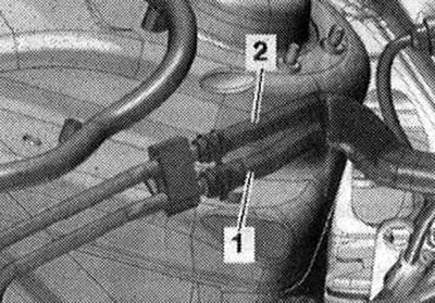
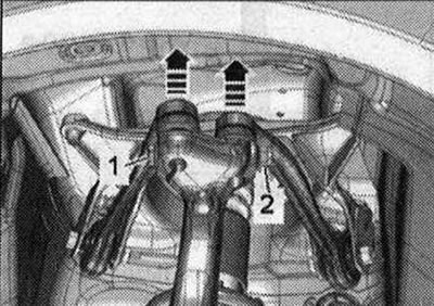
Disconnect fuel supply -1- and return -2- lines.
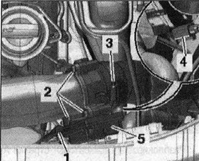
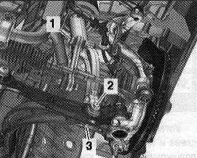
Remove plug -1-. Remove the air inlet hose by loosening the hose clamp -3-. Disconnect el. connector -4-. Unscrew bolts -2- and remove throttle valve module -J338- -item. 5-. Place a rag under the disconnect point to catch the escaping hydraulic oil.
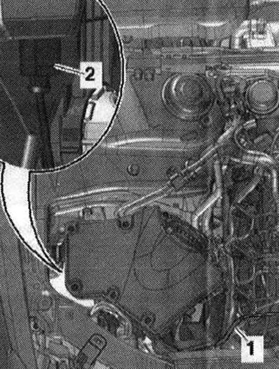
Clamp the hydraulic oil hose using a clamp -3094- and remove it from the vane pump -arrow-. -Pos. 1- do not take into account.
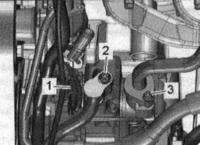
Unscrew the bolt -2-, remove the refrigerant line from the air conditioning compressor and place it aside. -Pos. 1, 3 - do not take into account.
Remove the coolant hose -3- from the radiator by lifting the clamping bracket. -Pos. 1, 2- and -arrows- are ignored.
Unscrew the bolts -1-, as well as the nuts -2- and -3-, and remove the extension.
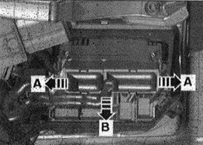
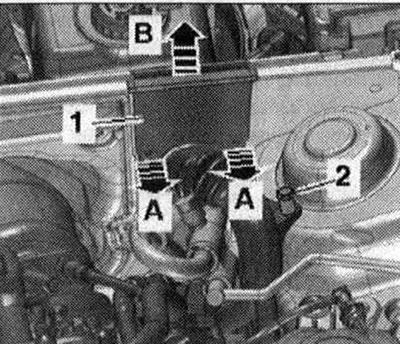
Remove gasket -3-. Release the mounting clips -1- from the mountings and remove the plenum chamber cover -2-.
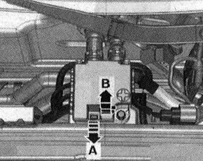
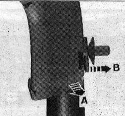
Unlock lock -arrow A- and open cover -arrow B-.
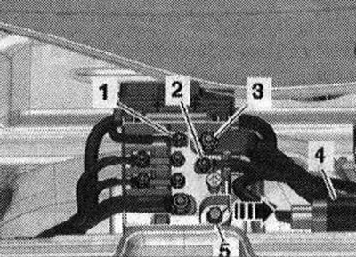
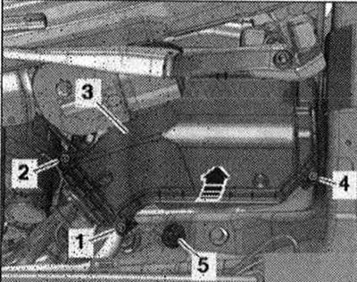
The nuts -1, 2, 3- el. are unscrewed. wires Remove connector -4- from bracket and disconnect it. Unscrew bolt -5- and remove splitter 2 cells. 30 -TV22- from the front wall of the plenum chamber -arrow-.
Remove the foam block -1 - towards the top. -Pos. 2- do not take into account.
Unlock the clamps from the wheel arch using a 5.5-pos. spanner. 1- and remove cable gland -2- upwards. Release the wiring harness -3- going to the alternator and starter using the release lever -80 - 200-.
Release the cable duct by unlocking the lock -arrow B- and moving the cable duct up -arrow A-.
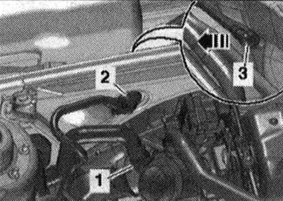
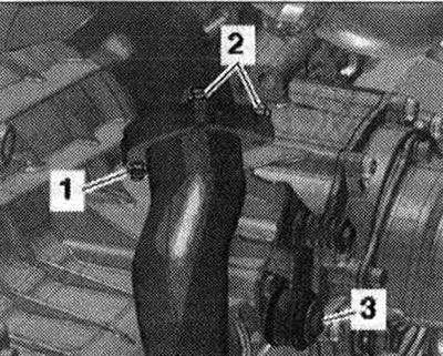
Disconnect coolant hose -1-. Remove the vacuum connection -2- from the end wall of the plenum chamber; to do this, disconnect the vacuum hose -3- at the rear -arrow-.
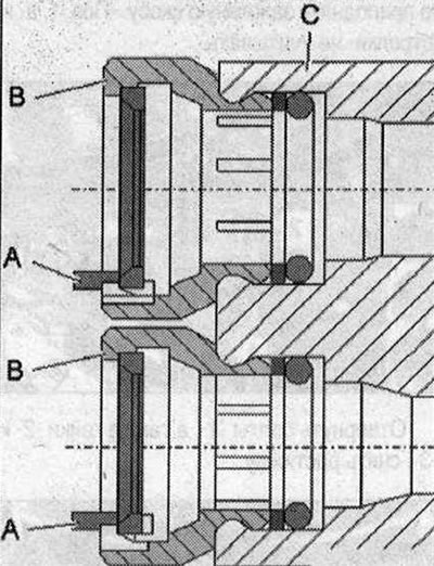
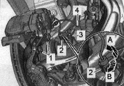
Insert the refrigerant lines -A- and -C- into the connection module -B- with internal heat exchanger by hand until they stop. Spray the area around the refrigerant lines with a silicone-free lubricant. Push the puller -T40149/1- onto the refrigerant line -A- and the puller -T40149/2- onto the refrigerant line -C- until you hear an audible click, thus releasing the fastenings. Using a puller, remove the coolant lines -A- and -C- from the pipe -BC using the coolant line with the internal heat exchanger.
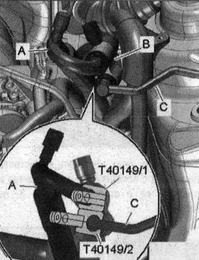
If the refrigerant lines cannot be removed, they must not be twisted in the connection module -C-. In this case, cut the connecting elements -B- and remove the retaining rings -A-. When cutting the connecting elements, be careful not to damage the connection module -C- with the internal heat exchanger.
Unscrew nut -3- and bolt -3-. Remove the filler neck -1- with the filler tube from the washer fluid reservoir by guiding it through the body opening -arrow-.
Unscrew bolts -1,2,4- and remove cover -3- of the engine switching unit. compartment Unscrew the nut -5- and release the ground wire.
Unlock the latches -arrows A- and remove the engine control unit -arrow B.
Disconnect (in the presence of) plug connector -2-. Disconnect plug connectors -4- and unscrew electrical wiring -3-. Unlock the latches -arrow ■ and remove the fuse block. B -SB- -pos. 1 -. Remove and release the engine wiring harness secured in the connection box.
Unlock latches -arrows A- and remove cable guide -1- upwards -arrow B-. Unscrew the ground bolt -2- and free the wiring harness. Place the wiring harness on the engine and secure the engine control unit from falling out.
Unscrew the nuts -2- of the exhaust pipe from above. Unscrew the nut -1- and bolt -3- last.
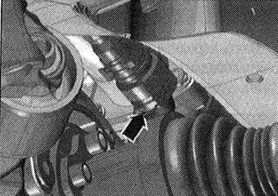
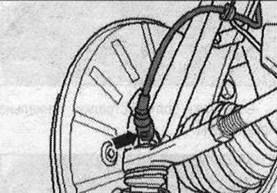
Disconnect the connector on the left and right of the front speed sensors -arrow-.
If present, disconnect the electrical connection. connectors -1- of the front left vehicle level sensor -G78- and the front right vehicle level sensor -G289- and release the electrical connection. cable -arrow-.
Disconnect the connector -2- from the bracket by pulling the locking pin backwards -arrow A- and turning the connector approx. 90°clockwise - arrow B-. Release el. wire -3- and brake hose -4- on the bracket. Unscrew the bolts -1- and hang the brake with wire. caliper on the wheel arch. Risk of damage to brake cylinder pistons. Do not press the brake pedal with the brake caliper removed.
Unscrew the nut -2- and remove the bolt -1-. Remove the upper suspension arm from the wheel bearing housing in an upward direction -arrows-. Repeat the entire process of performing work on the other side of the vehicle.
Unscrew bolts -1- of stabilizer on left and right. Unscrew nuts -3- on left and right. Unscrew bolts -2- last.
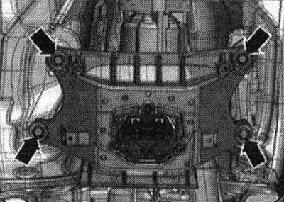
Unscrew the nut -1 - securing the hydraulic line of the power steering. Risk of damage to chassis components. If the engine mounting elements, steering gear or subframe crosspiece are installed improperly, the vehicle must not be placed on wheels. It is prohibited to support the vehicle by the subframe or subframe crosspiece (for example, a jack, etc.)! Unscrew the bolts -arrows- and remove the subframe extension.
Risk of damage to the Airbag coil spring contact. Disconnect the cardan joint with the cross from the steering mechanism only in the position of the front wheels for straight-line movement. Do not change the position of the steering wheel or the position of the steering gear. Unscrew the bolt -arrow- from the cardan joint with the crosspiece. Press the cardan joint with the cross from the steering mechanism and move the joint up until it stops.
Unscrew the nut -1- and bolt -3- of the exhaust pipe. The nuts -2- are already unscrewed.
Unscrew the screw connections -arrows-, push the clamping sleeve back and remove the exhaust pipe.
Press the ball head -2- of the gearbox selector cable using lever -80 - 200- from the shift shaft lever. Remove latch -1-. Release the selector cable. The gear selector cable must not be bent or bent.
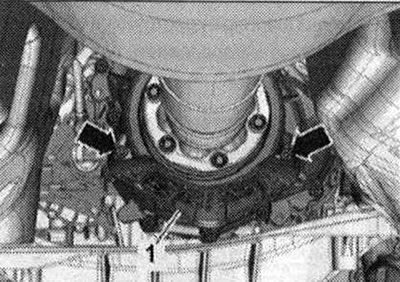
If present, unscrew the bolts -arrows- and remove the heat shield -1- for the propeller shaft.
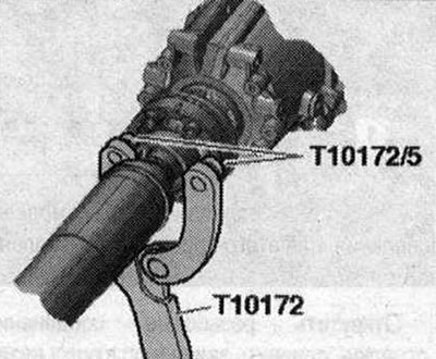
Unscrew the bolts securing the propeller shaft to the gearbox; to do this, hold the propeller shaft against turning with the support-T10172-c -T10172/5-. Move the driveshaft to the rear final drive housing; CV joints are movable in the axial direction. Secure the cardan shaft at the top.
Prepare the lifting table: Prepare the lifting table -VAS 6131 A- with a set of fastenings for Audi -VAS 6131 /10-, as well as additional accessories. set -VAS 6131 /11 - and -VAS 6131 /13 as follows. First screw the jigs onto the lifting table by hand. Position the lift table -VAS 6131 A- horizontally. Monitor the level (peephole) on the receiving platform. Place the lifting table -VAS 6131 A- under the power unit. Unscrew the bolts -1 - of the subframe on the left and right.
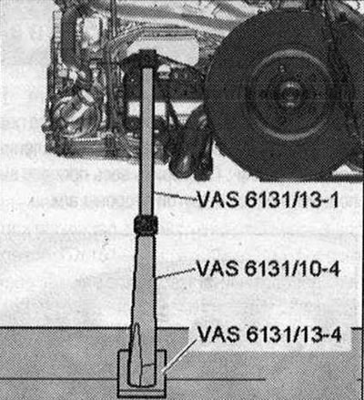
Install guides from -VAS 6131/10- and -VAS 6131/13- on the left and right of the front section of the subframe as shown in the illustration. Make sure that the lead screws are completely screwed in.
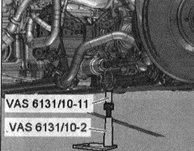
Install conductors from -VAS 6131/10 - rear left and right on the front threaded connections of the subframe extension, as shown in the illustration.
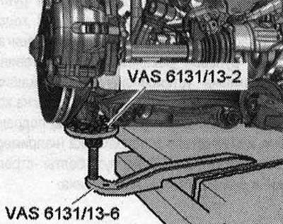
Install the jigs from -VAS 6131/13-left and right onto the lower part of the wheel bearing housing as shown in the illustration.
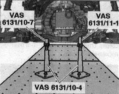
Install the guides from -VAS 6131/10- and -VAS 6131/11- at the rear left and right onto the tunnel cross member as shown in the illustration; Turn all the lead screws of the jigs up so that all the mounting lugs fit into the mounting points. Screw the support plates of the mounting elements with a torque of 20 Nm to the lift table -VAS6131 A-.
Mark with a felt-tip pen the installation position of the subframe on the side members. Unscrew the subframe bolts -2- and -3- crosswise in several stages. Bolts -1 are already unscrewed.
Unscrew the bolts -arrows- for the tunnel cross member.
Unscrew bolt -2- on left and right. Bolts -1- and nuts -3- have already been removed. Risk of damage to hose and cable connections as well as motor. compartment Make sure that all hose and wire connections between the engine, transmission, subframe and body are disconnected. When lowering, carefully remove the power unit with subframe from the engine. compartment
Lower the power unit down. Pull the lift table -VAS 6131 A- with the power unit out from under the vehicle.
Visitor comments