
Coolant hose connection diagram
Note: Blue = large coolant circuit. Red = small coolant circuit. Brown = heating circuit. Orange = cooling circuit for exhaust gas recirculation.
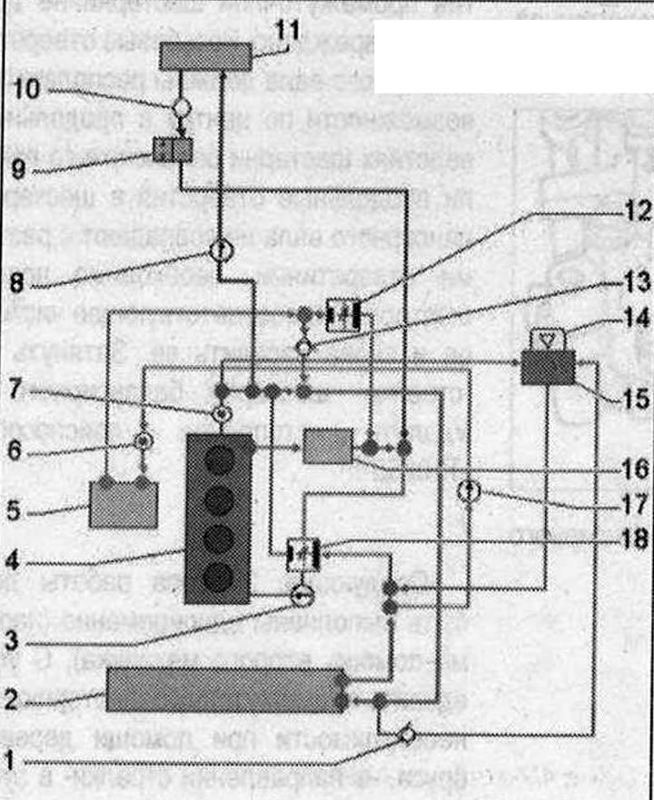
Coolant hose connection diagram 1. Check valve: the arrow indicates the direction of flow; 2. Coolant radiator: after replacement, change the coolant; 3. Coolant pump; 4. Cylinder head/cylinder block: after replacement, change the coolant; 5. EGR radiator: change coolant after replacement; 6. EGR temperature sensor "G98"; 7. Coolant temperature sensor "G62"; 8. Coolant circulation pump "V50": only for vehicles with start-stop system; 9. Coolant shut-off valve: vacuum-pressure-controlled coolant shut-off valve for Climatronic "N422"; 10. Ventilation hole; 11. Heater heat exchanger: after replacement, change the coolant; 12. EGR radiator thermostat; 13. Check valve: the arrow indicates the direction of flow; 14. Coolant expansion tank cap; 15. Coolant expansion tank: check the cooling system for leaks; 16. Oil radiator: after replacement, change the coolant; 17. EGR radiator pump "V400"; 18. 4/2-way valve with thermostat
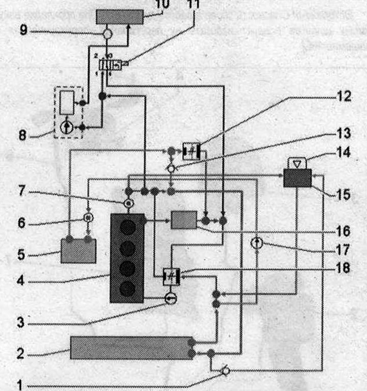
Car with independent heater 1. Check valve: the arrow indicates the direction of flow; 2. Coolant radiator: after replacement, change the coolant; 3. Coolant pump; 4. Cylinder head/cylinder block: after replacement, change the coolant; 5. EGR radiator: change coolant after replacement; 6. Temperature sensor of the exhaust gas recirculation system; 7. Coolant temperature sensor "G62"; 8. Autonomous heater; 9. Ventilation hole; 10. Heater heat exchanger: after replacement, change the coolant; 11. Heater coolant shut-off valve "N₂79"; 12. EGR radiator thermostat; 13. Check valve: the arrow indicates the direction of flow; 14. Coolant expansion tank cap; 15. Coolant expansion tank: check the cooling system for leaks; 16. Oil radiator: after replacement, change the coolant; 17. EGR radiator pump "V400"; 18. 4/2-way valve with thermostat
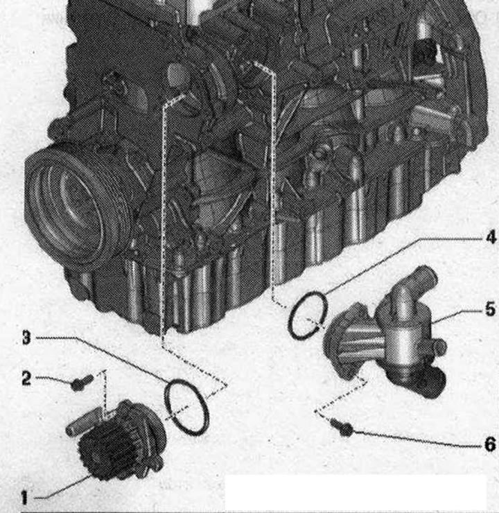
Coolant pump and 4/2-way valve 1. Coolant pump; 2/6. Bolt: 15Nm; 3. Sealing ring: replace; 4. Sealing ring: replace; 5. 4/2-way valve: The thermostat is located inside the 4/2-way valve and is not replaced separately
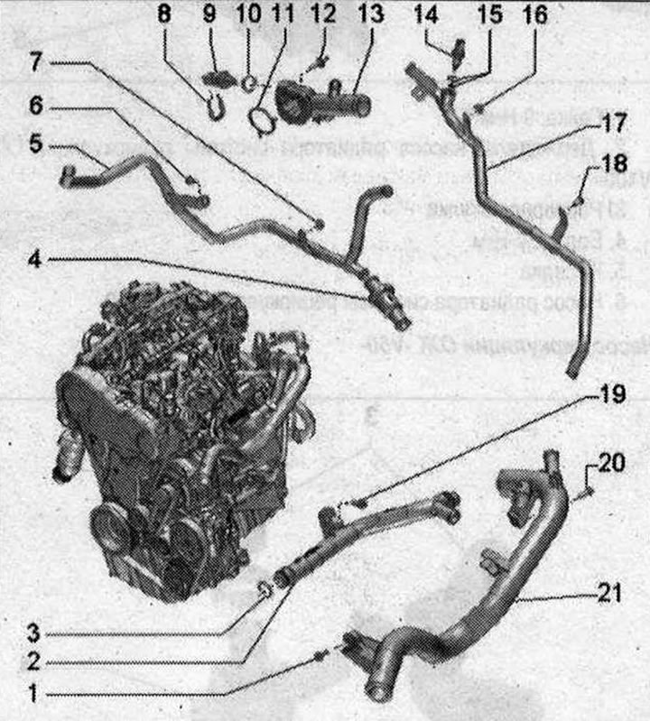
Coolant pipes, coolant temperature sensor, coolant circulation pump 1. Check valve: the arrow indicates the direction of flow; 2. Coolant radiator: after replacement, change the coolant; 3. Coolant pump; 4. Cylinder head/cylinder block: after replacement, change the coolant; 5. EGR radiator: change coolant after replacement; 6. Temperature sensor of the exhaust gas recirculation system; 7. Coolant temperature sensor "G62"; 8. Autonomous heater; 9. Ventilation hole; 10. Heater heat exchanger: after replacement, change the coolant; 11. Heater coolant shut-off valve "N₂79"; 12. EGR radiator thermostat; 13. Check valve: the arrow indicates the direction of flow; 1/6/12/18/19/20. Bolt: 9 Nm; 2. Left lower pipe of the cooling system; 3. Sealing ring: replace; 4. EGR radiator thermostat; 5. Coolant pipe, rear right; 7/16. Nut: 9 Nm; 8. Mounting bracket; 9. Coolant temperature sensor "G62"; 10. Sealing ring: replace; 11. Gasket: replace; 13. Connecting pipe of cooling system hoses; 14. Radiator outlet coolant temperature sensor "G83": 2 Nm; 15. Sealing rings: various diameters; replace; 17. Rear coolant pipe; 21. Left upper pipe of the cooling system
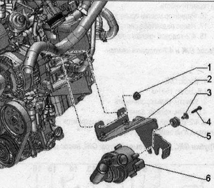
EGR radiator pump "V400". 1. Nut: 9 Nm; 2. Holder: EGR radiator pump "V400"; 3. Spacer sleeve; 4. Bolt: 2.7 Nm; 5. Nozzle; 6. EGR radiator pump "V400"
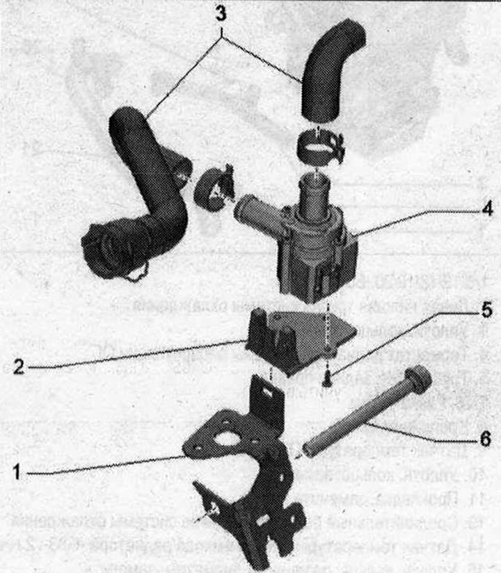
Coolant circulation pump "V50" 1. Holder; 2. Mounting plate; 3. Coolant hoses; 4. Coolant circulation pump "V50"; 5. Bolt: 2.7 Nm; 6. Bolt